Boost power supply sequencing

a power supply and sequencing technology, applied in the direction of electrical control, process and machine control, instruments, etc., can solve the problems of increasing the complexity of the controller (ecu), and achieve the effect of more flexibility

Active Publication Date: 2018-11-13
NATIONAL INSTRUMENTS
View PDF22 Cites 1 Cited by
  • Summary
  • Abstract
  • Description
  • Claims
  • Application Information

AI Technical Summary

Benefits of technology

[0010]In one set of embodiments, a variety of improvements are made to engine controllers for both passenger car and industrial engines. An engine control module (ECM) is proposed for an engine controller for advanced diesel engines. The ECM may perform all necessary engine control functions while accommodating a variety of new-concept injectors. In one set of embodiments, a proposed standalone direct injector driver module (SDIDM) may include the power electronics of the ECM, but without a portion of the engine I / O, packaging all features into an industrial form factor. The ECM and SDIDM modules are different from ordinary engine controllers found in current vehicles because they are designed for research and low volume production, with more flexibility than engine controllers found in production vehicles.
[0011]A boost power supply used in an engine control system may be constructed of a number of smaller switching power supplies, each switching power supply providing a respective portion (or portion current) of a combined output current provided by the boost power supply to a load. Each switching power may be controlled by a different respective control signal to regulate the respective portion current provided by the switching power supply, and the combined output current may be prevented from exceeding a specified threshold current value by applying each different respective control signal out of phase with respect to each other different respective control signal.

Problems solved by technology

The number of actuators to control, and the complexity of the controller (ECU) increased with each round of regulation, as the automotive electronics industry matured.

Method used


Image

  • Boost power supply sequencing
  • Boost power supply sequencing
  • Boost power supply sequencing

Examples


Embodiment Construction

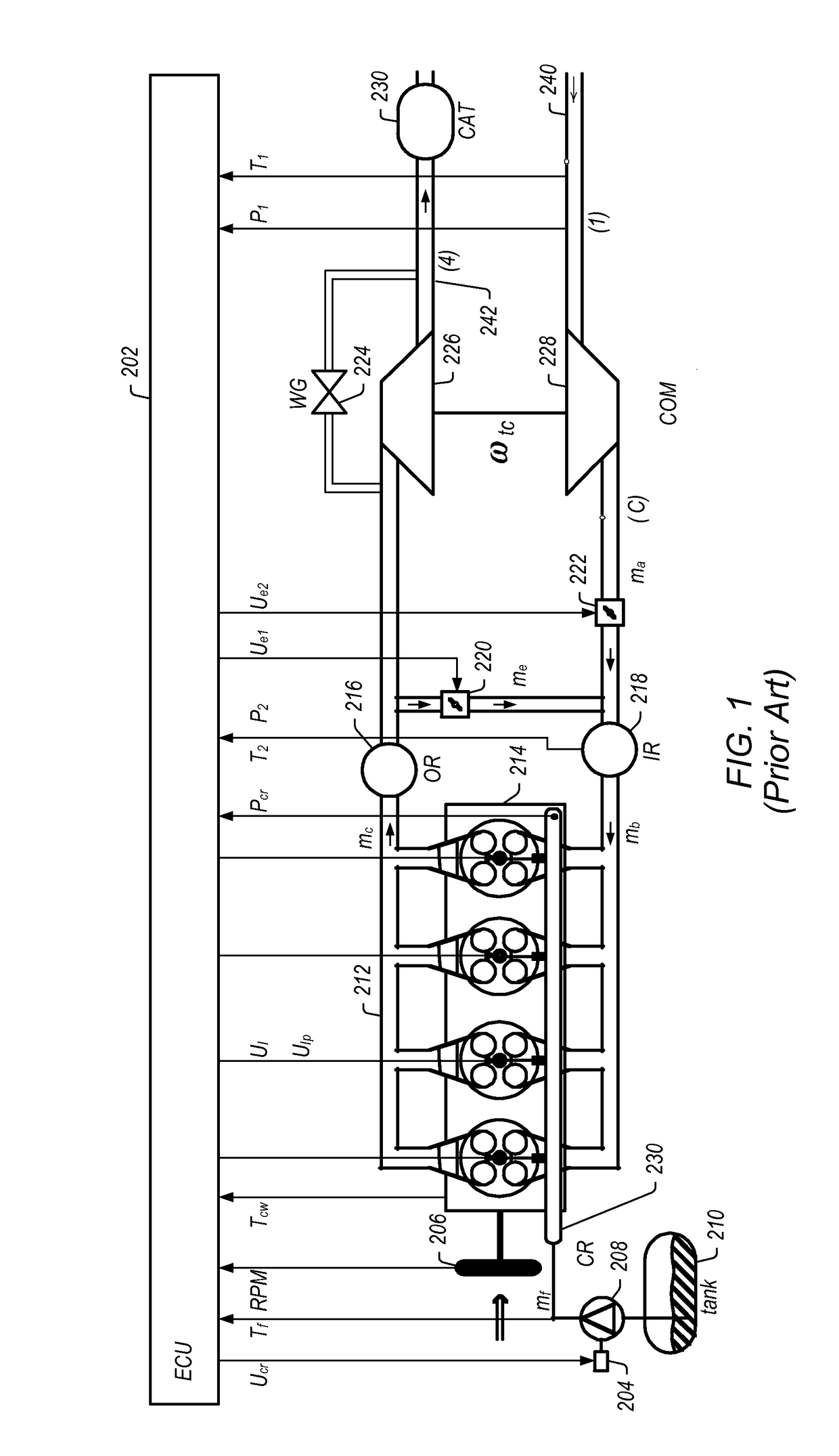
[0034]FIG. 1 shows a schematic diagram of one embodiment of a diesel engine system that includes an engine control unit (ECU) 202 with a subset of the input-output (I / O) used on ECU 202. Fresh air enters through pipe 240 in the direction shown, while the exhaust leaves via pipe 242 through catalyst (CAT) 230. Pressure and temperature are sampled before the compressor (COM) 226 / 228 in region (1). Air is compressed by the compressor 228 / 226 in region (C), where it may be gated by a throttle 222. The air is then mixed with a recirculated portion of the exhaust gas (EGR)—which is gated by throttle 220—in the intake manifold (IR) 218, where the pressure and temperature may be sampled as well. The mix of EGR and fresh air is then conveyed to the engine combustion chamber 214. Diesel fuel is pumped from the fuel tank 210 in to the common rail (CR) fuel system 208, from where it is provided to the injectors 230. At the correct engine angle, the fuel injectors 230 are fired by energizing a s...


PUM


Abstract

A boost power supply may be constructed of a number of smaller switching power supplies, each switching power supply providing a respective portion of a combined output current provided by the boost power supply to a load. A different respective control signal may be provided to each switching power supply to regulate the respective portion of the combined output current provided by the switching power supply. Each different respective control signal may be provided to the corresponding switching power supply out of phase with respect to each other different respective control signal to prevent the combined output current from exceeding a specified threshold current value.

Description

PRIORITY CLAIM[0001]This application claims benefit of priority of U.S. provisional application Ser. No. 61 / 720,005 titled “Boost Power Supply Sequencing”, which was filed on Oct. 30, 2012, and which is hereby incorporated by reference in its entirety as though fully and completely set forth herein.BACKGROUND OF THE INVENTION[0002]Field of the Invention[0003]This invention relates generally to engine controllers and, more particularly, to boost power supply sequencing.[0004]Description of the Related Art[0005]Most present day internal combustion engines, or other type of automotive or general-purpose engines are controlled using engine control units (ECUs). Typically, an ECU is an electronic, oftentimes computerized or computer-directed control unit operated to read feedback values from a number of sensors situated within and around the engine (e.g. in the engine bay for vehicles), and interpret the feedback data using multidimensional performance maps and computational models, e.g....

Claims


Application Information

Patent Timeline
Patent Type & Authority Patents(United States)
IPC IPC(8): G05F1/00F02D41/02F02D41/20F02D41/26H02M3/158
CPCF02D41/02F02D41/20F02D41/26H02M3/1584H02M2003/1586F02D2041/2006F02D2041/2013F02D2041/2027F02D2400/14F02D2041/2003H02M3/1586
Inventor VIELE, MATTHEWDASE, CARROLL G.
Owner NATIONAL INSTRUMENTS
Why Eureka
Try Eureka