Fabric for forming a paper web having an embossed surface

a technology of fibrous paper and embossed surfaces, which is applied in the field of fabric for forming fibrous paper webs with embossed surfaces, can solve the problems of inability to manufacture paper webs with voluminous embossings, affecting the drainage of paper webs, and high cost of fabrics

Inactive Publication Date: 2013-08-29
HEIMBACH GMBH & CO KG
View PDF8 Cites 3 Cited by
  • Summary
  • Abstract
  • Description
  • Claims
  • Application Information

AI Technical Summary

Benefits of technology

[0014]The advantage of this concept is that all of the longitudinal thread groups can be adapted optimally to their respective functions with regard to their binding into the woven fabric layers, their materials and their cross sections. The arrangement of the second longitudinal threads to outer and inner longitudinal threads enable a functional separation in the sense that by being guided principally on the outer side of the second woven fabric layer, the outer longitudinal second threads can essentially serve to provide a high volume for abrasion resistance, whereas the inner longitudinal second threads essentially determine the tensile strength of the entire fabric and are thus protected from contact with machine elements and so from abrasion. Therefore, the wear arising due to the circulation of the woven fabric with the outer longitudinal second threads has less of an effect upon the overall tensile strength of the woven fabric because the tensile forces are largely absorbed by the inner longitudinal second threads. Consequently, the tensile strength of the entire fabric is largely maintained due to the protected extension of the inner second longitudinal threads over the operating time of the fabric.

Problems solved by technology

With the design of the fabrics as disclosed in the foregoing documents, it is not possible to manufacture paper webs with voluminous embossings.
However, this kind of fabrics is expensive to manufacture and has a drainage characteristic, which impairs the drainage of the paper web particularly when it is used in the wet forming section.

Method used


Image

  • Fabric for forming a paper web having an embossed surface
  • Fabric for forming a paper web having an embossed surface
  • Fabric for forming a paper web having an embossed surface

Examples


second embodiment

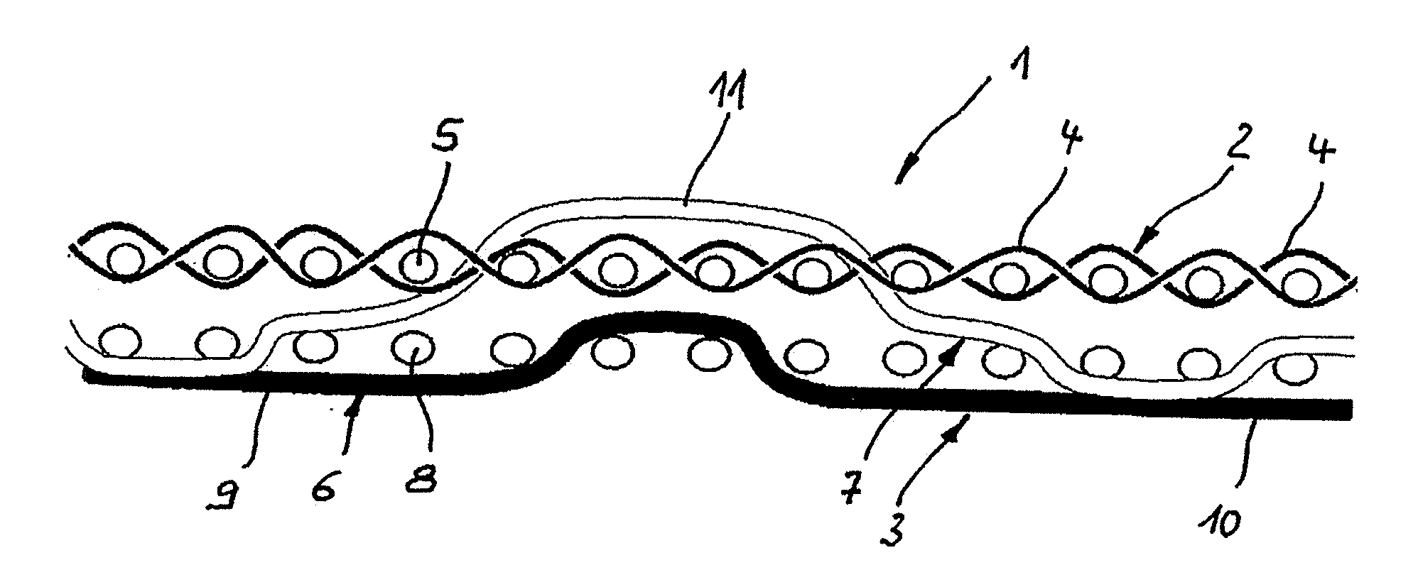
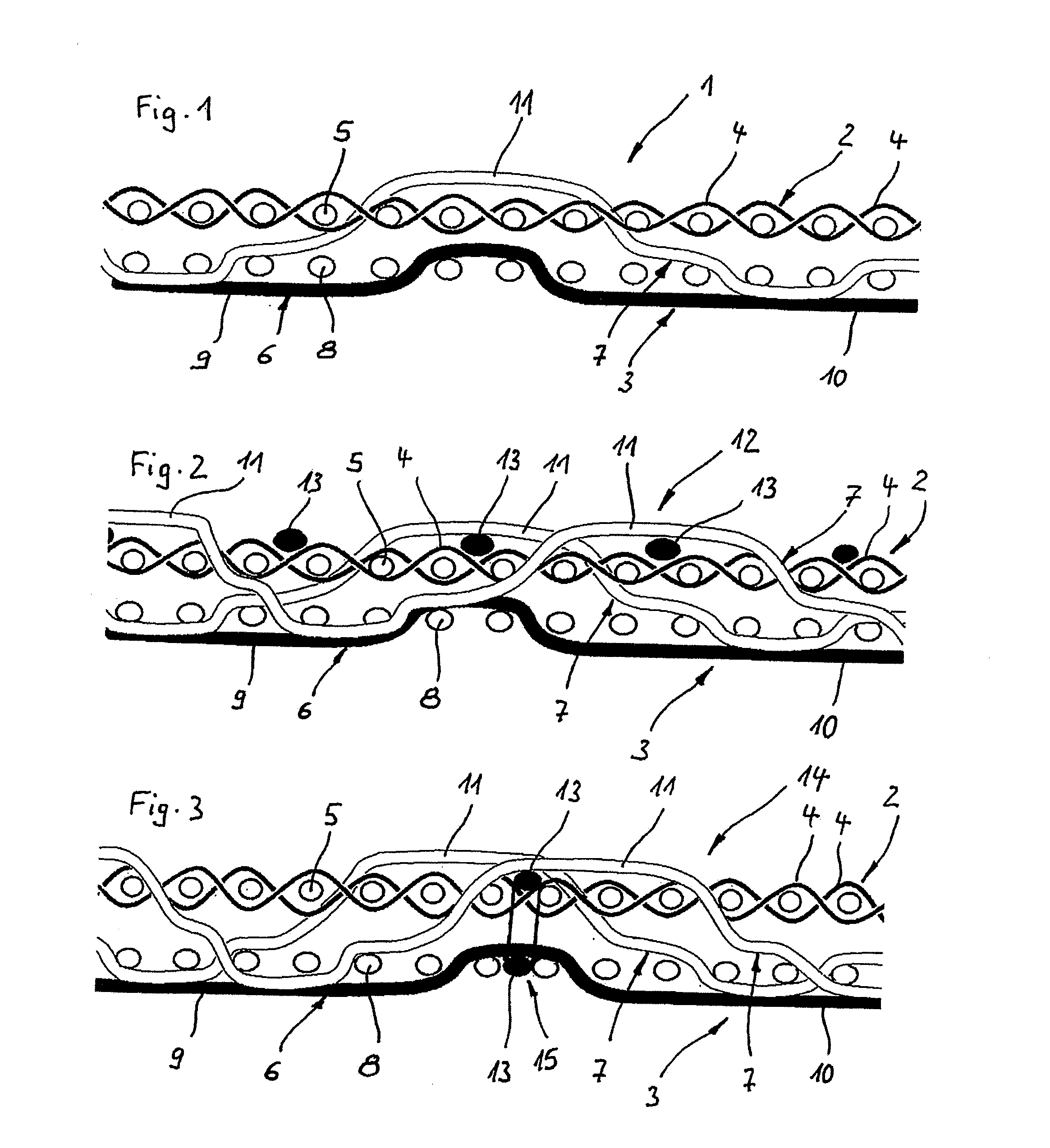
[0040]the invention shown in FIG. 2 has a similar structure as to the fabric 1 illustrated in FIG. 1. Hence, the same reference numbers are used for the second fabric 12, and it is made reference to the description of the first fabric 1 with respect to the parts provided with the same reference numbers. In FIG. 2, not only one embossing thread 7 is shown but two embossing threads 7 extending adjacently and being offset to one another about three transverse first and second threads 5, 8 such that one transverse first thread 5 is enclosed by two adjacent embossing threads 7, one of which is penetrating in the direction to the paper side and one of which is penetrating in the direction to the second woven fabric layer 3.

[0041]The only difference between the first fabric 1 and the second fabric 12 is that additional transverse third threads 13 are laid over the paper side of the first woven fabric layer 2 between two adjacent transverse first threads 5 respectively. The transverse third...

fourth embodiment

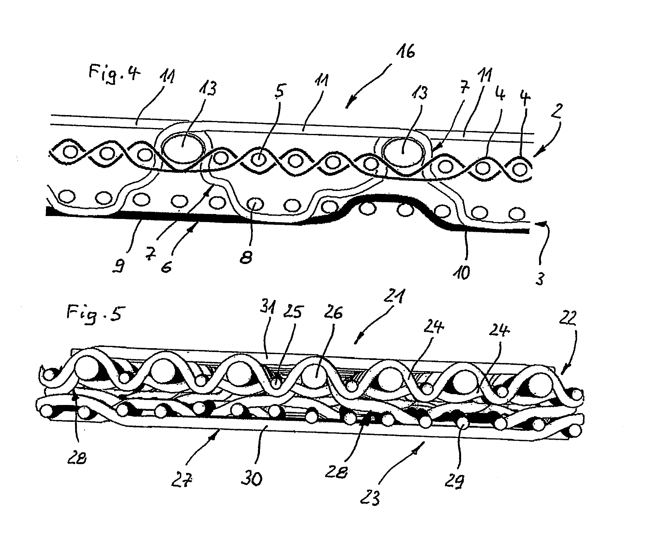
[0045]FIG. 4 shows fabric 16 according to the invention. The fabric 16 is designed similar to the fabrics 1, 12, 14 as shown in the foregoing figures. So, the same reference numbers are used for the according parts of these fabrics 1, 12, 14, and for describing these parts it is referred to the description of the fabrics 1, 12 and 14.

[0046]Fabric 16 is provided with transverse third threads 13, however in this case replacing every sixth transverse first thread 5, being laid onto the first woven fabric layer 2 and hence, not being bound therein. Consequently, all the longitudinal first threads 4 pass under the inner side of the longitudinal third threads 13 thus forming recesses for them. The transverse third threads 13 have an overall cross-section being much thicker than the cross-sections of the transverse first threads 5. The paper side floats 11 of the embossing threads 7 extend first over one transverse third thread 13 after penetrating the first woven fabric layer 2, then pass...

fifth embodiment

[0047]FIG. 5 shows another fabric 21 (fifth embodiment) having a first woven fabric layer 22 and a second woven fabric layer 23 superimposed one over the other.

[0048]The first woven fabric layer 22 comprises longitudinal first threads 24 and transverse threads, namely transverse first threads—for example identified by 25—and transverse third threads—for example identified by 26—, all of which have circular cross-sections. The transverse first threads 25 alternate with the transverse third threads 26. The longitudinal first threads 24 on the one hand and the transverse first and third threads 25, 26 on the other hand are interwoven with one another to form a plain weave, i.e. one longitudinal first thread 24 binds a transverse first thread 25 on its paper side and a subsequent transverse third thread 26 on its inner side, while the adjacent longitudinal first thread 24 binds a transverse first thread 25 on its inner side and a subsequent transverse third thread 26 on its paper side.

[...


PUM


Abstract

The invention relates to a fabric for forming a fibrous paper web having an embossed surface. The fabric comprises longitudinal and transverse threads interwoven with one another in a weave repeat defining a machine side and a paper side. Some of the longitudinal threads form embossing threads having projecting paper side floats on the paper side of the fabric passing over more than one transverse thread. The fabric comprises a first woven fabric layer forming the paper side on its outside and having longitudinal and transverse first threads interwoven with one another and a second woven fabric layer forming the machine side on its outside and having longitudinal and transverse second threads interwoven with one another. At least some of the longitudinal second threads form embossing threads, which penetrate the first woven fabric layer for forming the paper side floats and connect the two woven fabric layers.

Description

CROSS-REFERENCE TO RELATED APPLICATIONS AND CLAIM TO PRIORITY[0001]This application is related to patent application number 12 159 912.3, filed Feb. 24, 2012 in the European Patent Office, the disclosure of which is incorporated herein by reference and to which priority is claimed.FIELD OF THE INVENTION[0002]The invention relates to a fabric for forming a fibrous paper web having an embossed surface, the fabric comprising longitudinal and transverse threads interwoven with one another in a weave repeat unit defining a machine side and a paper side, wherein longitudinal threads form embossing threads having projecting paper side floats on the paper side of the fabric passing over transverse threads.BACKGROUND OF THE INVENTION[0003]For the manufacture of patterned paper like tissue products such as facial and bath tissue and paper towels or of other non-woven materials, it is known to use fabrics in the paper making machine being employed in making embossed or patterned paper webs pro...

Claims


Application Information

Patent Timeline
Patent Type & Authority Applications(United States)
IPC IPC(8): D03D1/00
CPCD21F1/0036D03D1/00D21F11/006D03D11/00D21F7/00
Inventor BARRETT, REXRIGBY, ALISTER JOHN
Owner HEIMBACH GMBH & CO KG
Why Eureka
Try Eureka