Valve assembly for controlling coolant flow exiting an engine

a valve assembly and coolant technology, applied in the direction of valves, mechanical equipment, machines/engines, etc., can solve the problems of reducing engine efficiency under certain operating conditions, affecting the physical geometry of conventional thermostats, and disadvantages of using thermostats in conventional fluid handling systems

Inactive Publication Date: 2003-12-09
DANA AUTOMOTIVE SYST GRP LLC
View PDF27 Cites 32 Cited by
  • Summary
  • Abstract
  • Description
  • Claims
  • Application Information

AI Technical Summary

Benefits of technology

A valve assembly in accordance with the present invention includes a valve housing mounted to the engine and having a passage extending therethrough. The valve housing may be mounted to a variety of engine components including the engine block, the cylinder head, a crossover casting, or the intake manifold. The passage of the valve housing is in fluid communication with a coolant outlet in the engine. The assembly also includes a motor disposed within the valve housing. The motor includes a motor shaft extending therefrom. The assembly also includes a valve shaft configured to rotate responsive to rotation of the motor shaft. The valve shaft maybe driven through one or more gears disposed between the motor and valve shafts. Finally, the assembly includes a plate rotatably supported on the valve shaft within the passage defined in the valve housing. The rotational position of the plate controls the amount of coolant exiting the engine.
A valve assembly in accordance with the present invention has several advantages as compared to conventional devices for controlling coolant exiting an engine. First, engine coolant temperature has less of an effect on the inventive valve assembly than on conventional thermostats. As a result, the inventive valve assembly allows little if any coolant to pass prior to the temperature at which the valve assembly is designed to open. Engine efficiency is therefore increased resulting in greater fuel economy and reduced engine emissions. Second, the inventive assembly tolerates contamination from the engine coolant better than conventional devices and therefore has a greater lifespan and requires less maintenance than conventional devices. Third, the inventive assembly integrates the valving member and the components that drive the valving member in a single assembly that is directly coupled to the engine. In this manner, the inventive assembly improves packaging, requires less material, reduces potential coolant leak points and improves bearing alignment for the valve shaft.

Problems solved by technology

The use of a thermostat in conventional fluid handling systems is disadvantageous.
In particular, the physical geometry of conventional thermostats is affected by the temperature of the engine coolant.
This reduces engine efficiency under certain operating conditions because the engine cannot reach a desired operating temperature as quickly as desired.
First, engine coolant temperature has less of an effect on the inventive valve assembly than on conventional thermostats.
As a result, the inventive valve assembly allows little if any coolant to pass prior to the temperature at which the valve assembly is designed to open.
Second, the inventive assembly tolerates contamination from the engine coolant better than conventional devices and therefore has a greater lifespan and requires less maintenance than conventional devices.

Method used


Image

  • Valve assembly for controlling coolant flow exiting an engine
  • Valve assembly for controlling coolant flow exiting an engine
  • Valve assembly for controlling coolant flow exiting an engine

Examples


Embodiment Construction

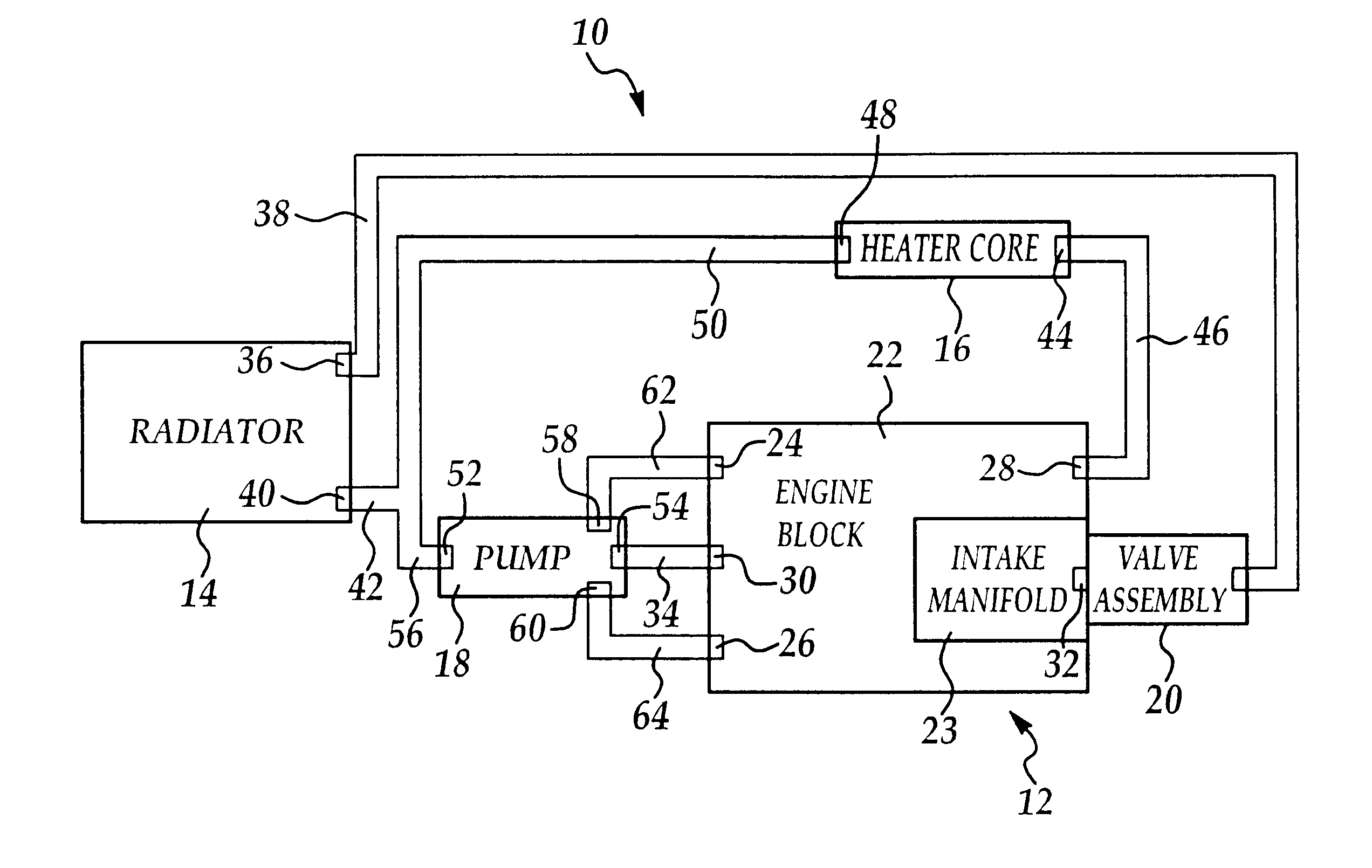
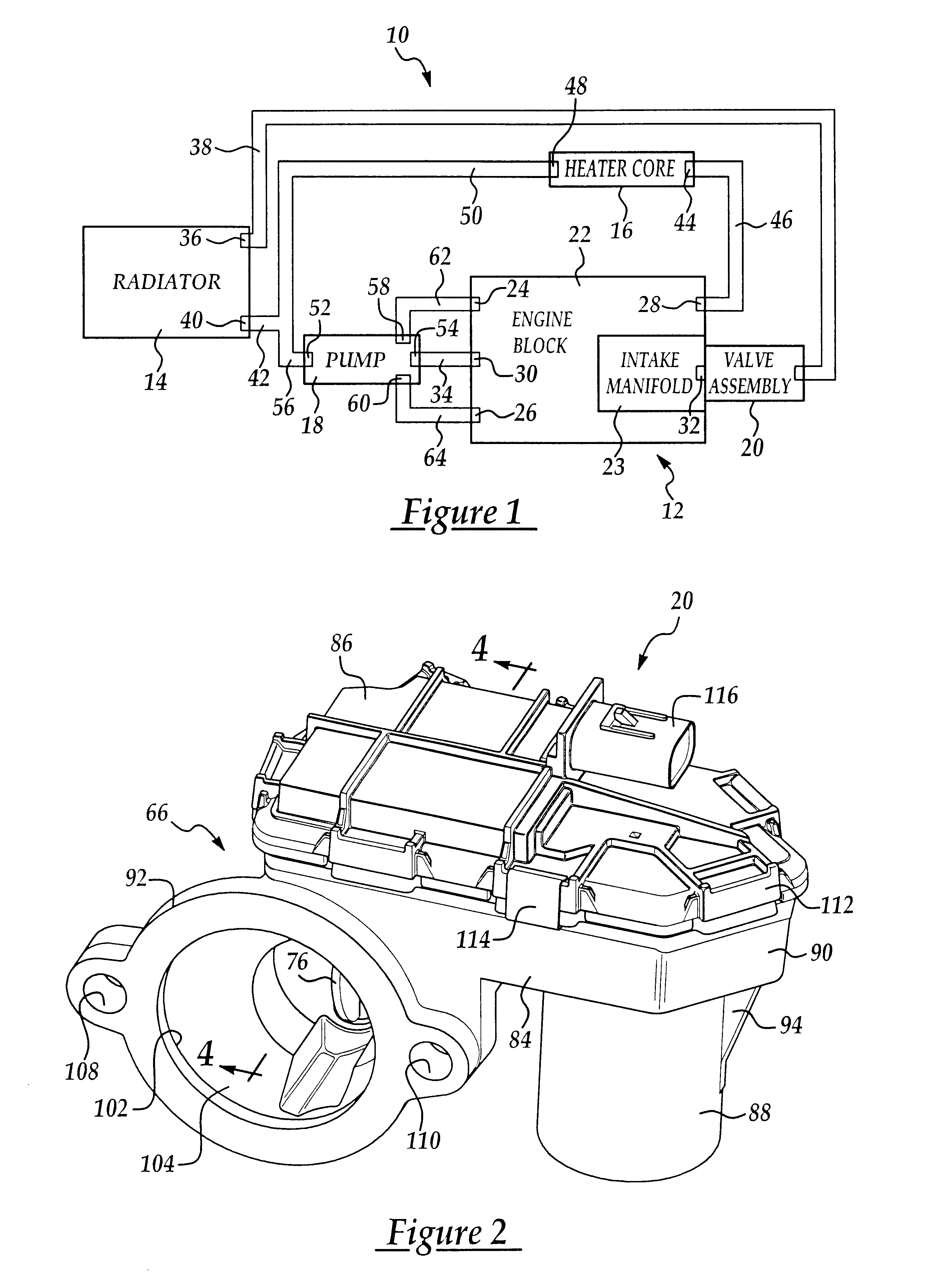
Referring now to the drawings wherein like reference numerals are used to identify identical components in the various views, FIG. 1 illustrates a fluid handling system 10 for a vehicle having an engine 12, a radiator 14, a heater core 16, a pump 18, and a valve assembly 20 in accordance with the present invention. Although the inventive valve assembly 20 will be described with respect to a vehicle fluid handling system 10, it should be understood that the inventive valve assembly may find use in a wide variety of applications in which engines are used to provide power and are cooled by fluids flowing through the engine.

Engine 12 provides motive power to the vehicle and may comprise any of a wide variety of conventional engines. Engine 12 may include an engine block 22, a cylinder head (not shown), a crossover casting, and intake manifold 23 that together define a plurality of cylinders (not shown) and fluid passages (not shown) configured to allow an engine coolant to circulate wit...


PUM


Abstract

A valve assembly for controlling the amount of coolant exiting an engine is provided. The valve assembly includes a valve housing that is mounted to the engine and defines a passage that is in fluid communication with a coolant outlet in the engine. A motor in the valve housing drives a valve shaft that extends into the passage and on which a butterfly valve plate is mounted. The physical geometry of the inventive assembly is not significantly effected by changes in coolant temperature or coolant contamination and the integrates the valve member and actuator in a single assembly to improve packaging and material use and eliminates potential coolant leak points.

Description

1. Field of the InventionThis invention relates to fluid handlin; systems in vehicles and, in particular, to a valve assembly for controlling tile flow of coolant exiting a vehicle engine.2. Discussion of Related ArtIn a conventional vehicle fluid handling system, engine coolant travels between a vehicle engine, a radiator, and a hearer core. In particular, coolant is provided So the engine and heat is transferred from the engine to the coolant. Upon exiting the engine, the coolant flows to one or both of the radiator and the heater core. Heat is then vented into the air by the radiator or into the passenger compartment of the vehicle by the heater core, respectively. Finally, the coolant returns from the radiator and / or heater core to a pump that provides the coolant to the engine again.The flow of coolant from the engine to the radiator is typically regulated using a thermostat. The thermostat controls the amount of coolant flowing from the engine to the radiator responsive to the...

Claims


Application Information

Patent Timeline
Patent Type & Authority Patents(United States)
IPC IPC(8): F01P7/16F01P7/14F16K31/04F16K1/22
CPCF01P7/167F16K31/043F16K1/221F01P2060/08F01P2060/10
Inventor CREECH, MICHAELHAUCK, REED K.WEIS, PHILLIP JAMES
Owner DANA AUTOMOTIVE SYST GRP LLC
Why Eureka
Try Eureka