

Pneumatic tire
a technology of pneumatic tires and tires, applied in the field of pneumatic tires, can solve the problems of difficult to increase the rigidity of the land portion (d), and achieve the effect of improving the wet performance and steering stability during running
Active Publication Date: 2013-08-29
SUMITOMO RUBBER IND LTD
View PDF3 Cites 17 Cited by
- Summary
- Abstract
- Description
- Claims
- Application Information
AI Technical Summary
Benefits of technology
[0009]It is therefore, an object of the present invention to provide a pneumatic tire, in which high-speed running
Problems solved by technology
Therefore, it is difficult to increase the rigidity of the land portion (d
Method used
View moreImage
Smart ImageViewing Examples

Examples
 PUM
 Abstract
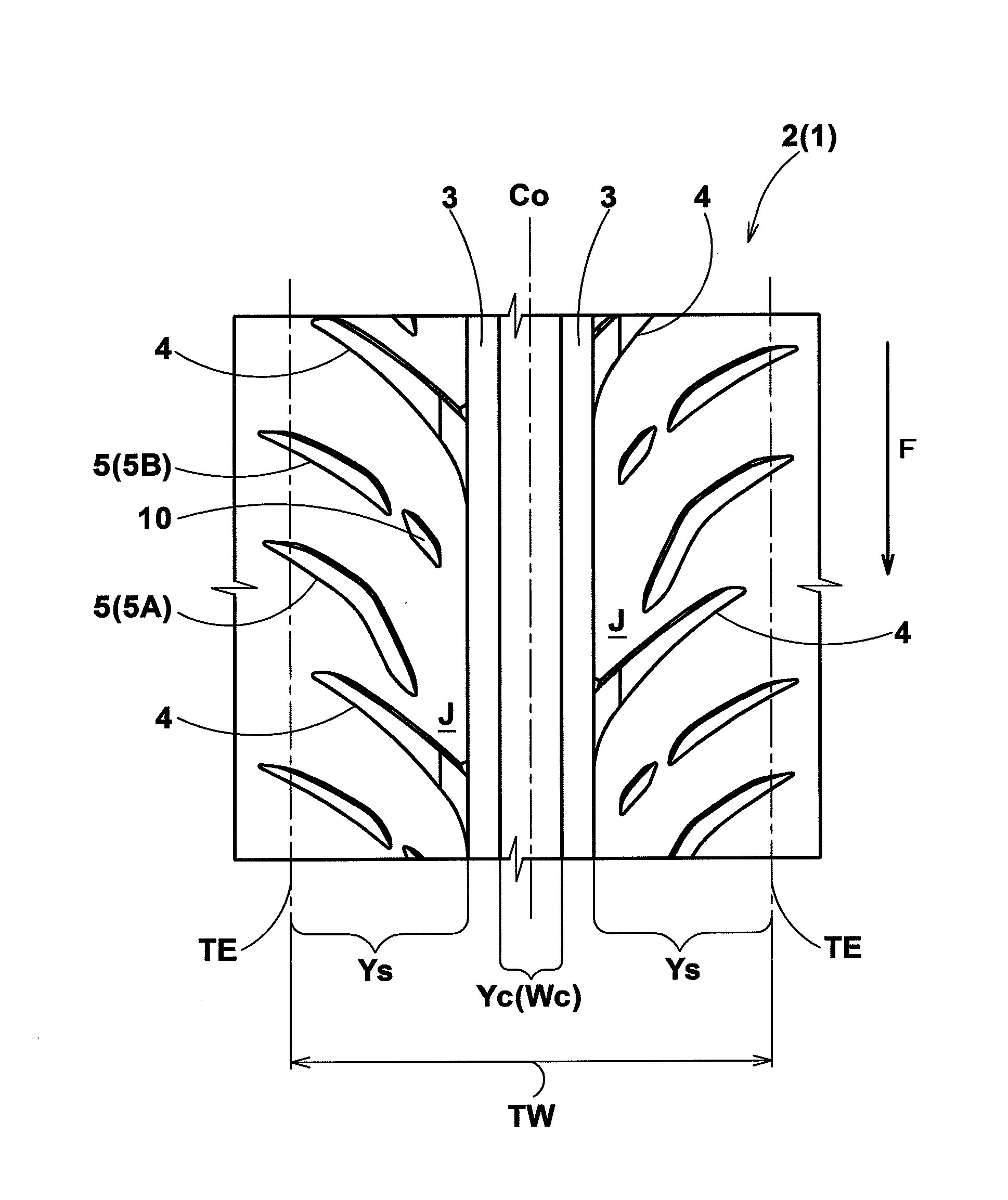
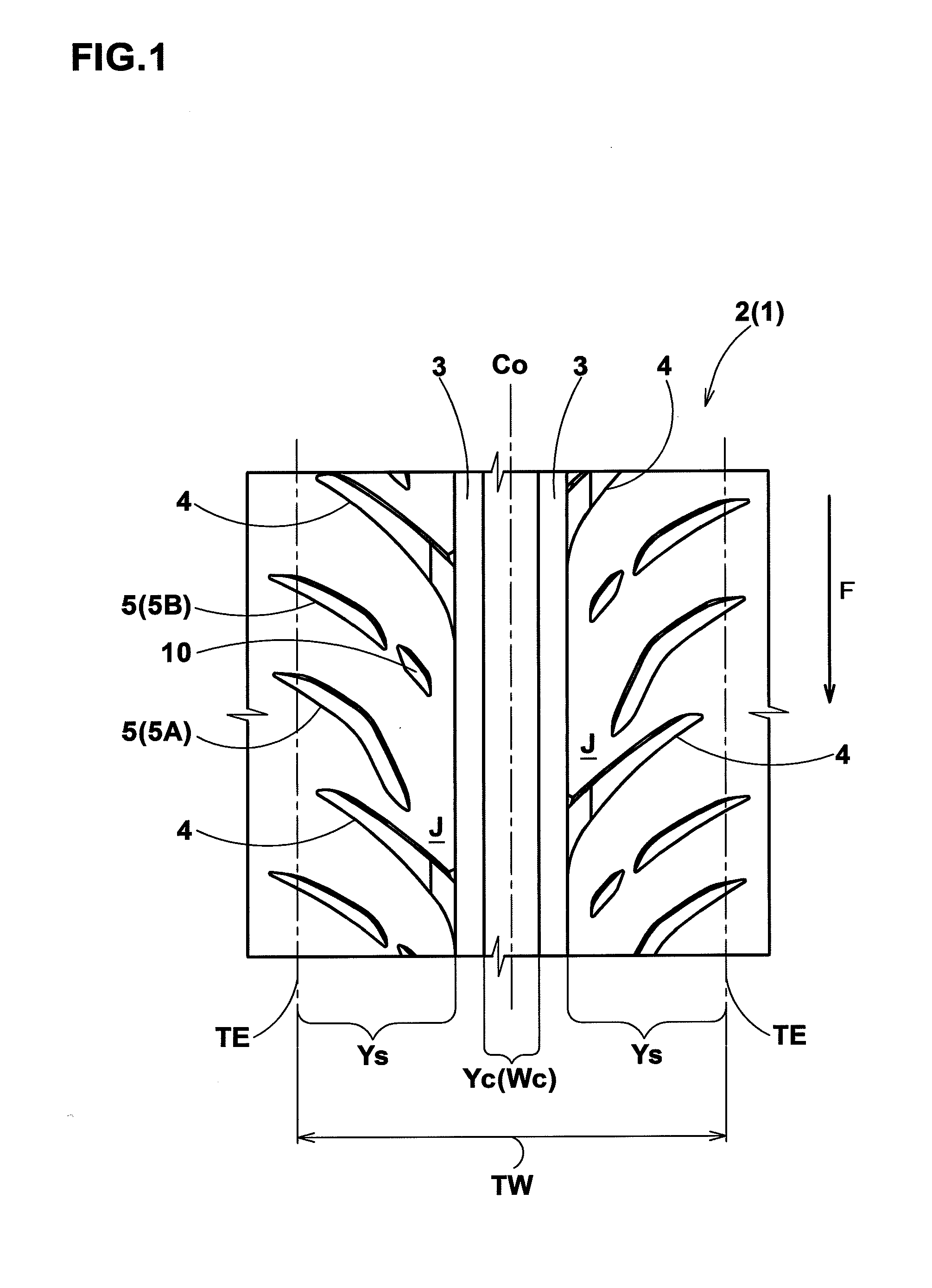
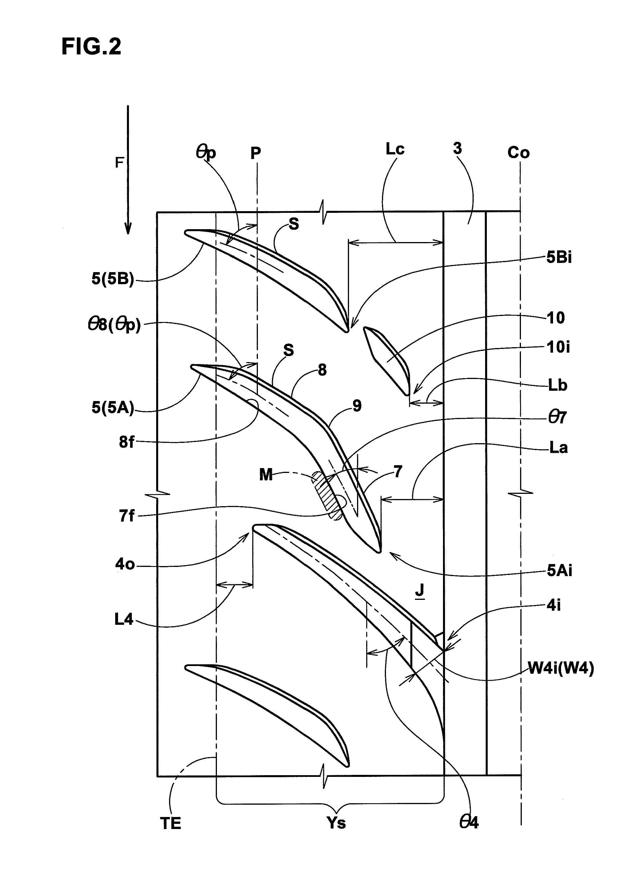
A pneumatic tire has: a circumferential groove on each side of the tire equator; oblique grooves extending from the circumferential groove while inclining to one circumferential direction; and lug grooves extending axially outwardly beyond the tread edges from positions axially outside the circumferential groove while inclining to the one circumferential direction. The lug grooves include: a first lug groove comprising an axially inner steeply-inclined part and an axially outer mildly-inclined part; and a second lug groove extending along the mildly-inclined part. The axially inner end of the first lug groove is at a distance La of 8 to 12% of the tread width from the circumferential groove. The steeply-inclined part inclines at an angle larger than an inclination angle of the oblique grooves.
Description
BACKGROUND OF THE INVENTION[0001]The present invention relates to a pneumatic tire, more particularly to a tread pattern capable of improving high-speed running performance, especially steering stability during running in a racing circuit, as well as wet performance.[0002]Japanese Patent Application Publication No. 2009-101785 discloses a pneumatic tire having a tread pattern shown in FIG. 5, wherein a circumferential groove (a) is disposed on each side of the tire equator Co, and main oblique grooves (b) and auxiliary oblique grooves (c) are disposed axially outside the circumferential groove (a) and arranged alternately in the tire circumferential direction. The main oblique groove (b) and auxiliary oblique groove (c) each have an axially outer end positioned axially outside the tread edge E1.[0003]The axially inner end of the auxiliary oblique groove (c) is located far from the circumferential groove (a), but the axially inner end of the main oblique groove (b) is located very cl...
Claims
Login to View More Application Information
Patent Timeline
 IPC IPC(8): B60C11/117
CPCB60C11/04B60C11/1369B60C11/1392B60C2011/0388B60C11/0302B60C2011/0372B60C2011/0358B60C2011/0369B60C11/1323B60C11/1307B60C2011/0381B60C11/032B60C11/03B60C11/13B60C2011/0341B60C2011/0374
InventorSANAE, RYUHEI
OwnerSUMITOMO RUBBER IND LTD