Window Shade and Its Control Module

a technology for controlling modules and windows, which is applied in the direction of door/window protective devices, building components, construction, etc., can solve the problems of increasing the length of the operating cord, the risk of child strangulation on the longer operating cord, and the less convenient manipulation of the longer operating cord. , to achieve the effect of reducing the risk of child strangulation, convenient adjustment of the shade, and shortening the length

Active Publication Date: 2013-08-29
TEH YOR CO LTD
View PDF44 Cites 56 Cited by
  • Summary
  • Abstract
  • Description
  • Claims
  • Application Information

AI Technical Summary

Benefits of technology

[0010]The invention describes a window shade and a control module suitable for use with the window shade. The construction of the control module can use a shorter length of an operating cord for raising a shading structure of the window shade. The control module also includes an actuator that is easily operable to turn the control module from a locking state to an unlocking state for lowering a bottom part of the window shade.
[0013]At least one advantage of the window shade described herein is the ability to conveniently adjust the shade by respectively operating the operating cord and the actuator. The operating cord used for raising the window shade has a shorter length, which can reduce the risk of child strangulation. The window shade can also be easily lowered by rotating the actuator.

Problems solved by technology

However, this conventional construction may require to use an increased length of the operating cord for window shades that have greater vertical lengths.
Moreover, there is the risk that a child may be strangled on a longer operating cord.
Unfortunately, when the operating cord is pulled downward to raise the window shade, the operating cord may still move to a lower position and become accessible for a child.
With respect to a regular user, the manipulation of longer operating cords may also be less convenient.
For example, the longer operating cord may become entangled, which may render its operation difficult.

Method used


Image

  • Window Shade and Its Control Module
  • Window Shade and Its Control Module
  • Window Shade and Its Control Module

Examples


Embodiment Construction

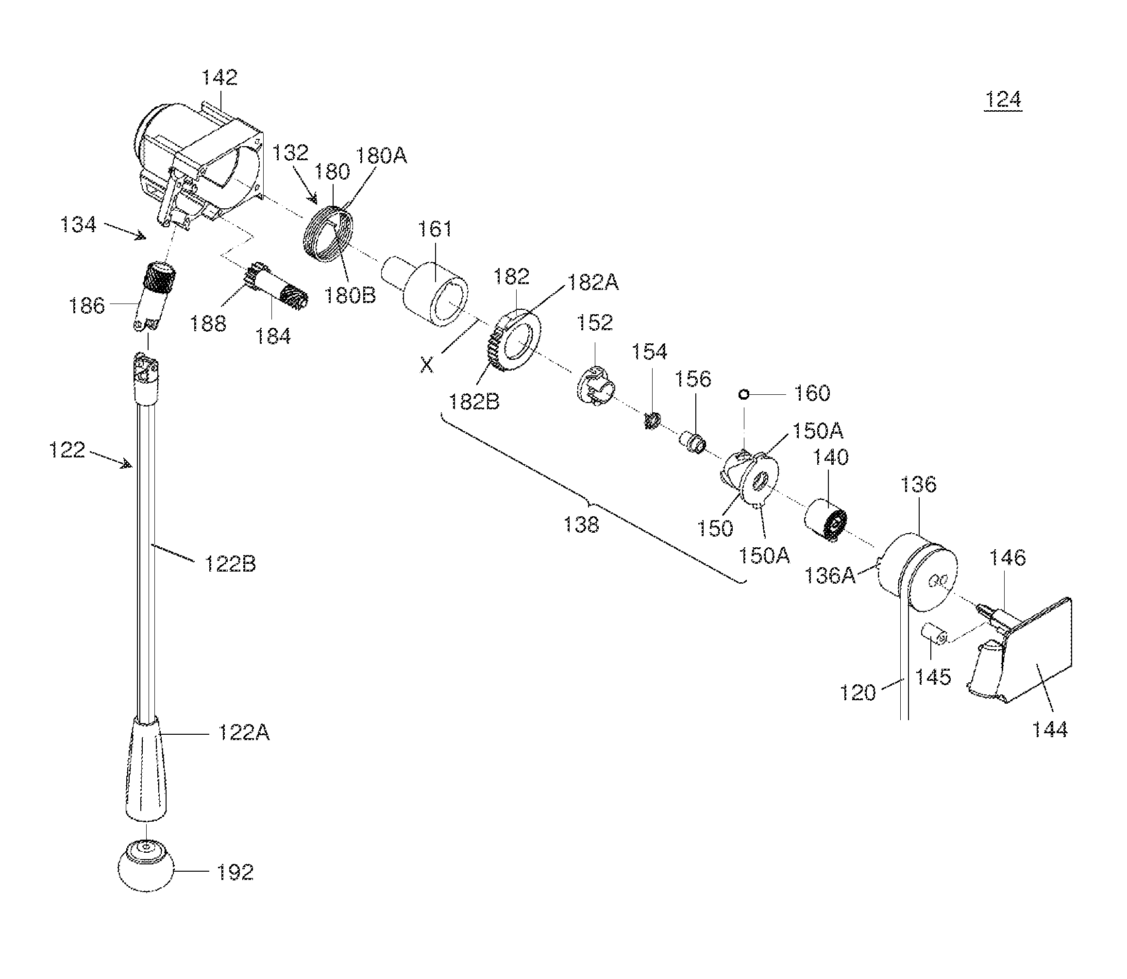
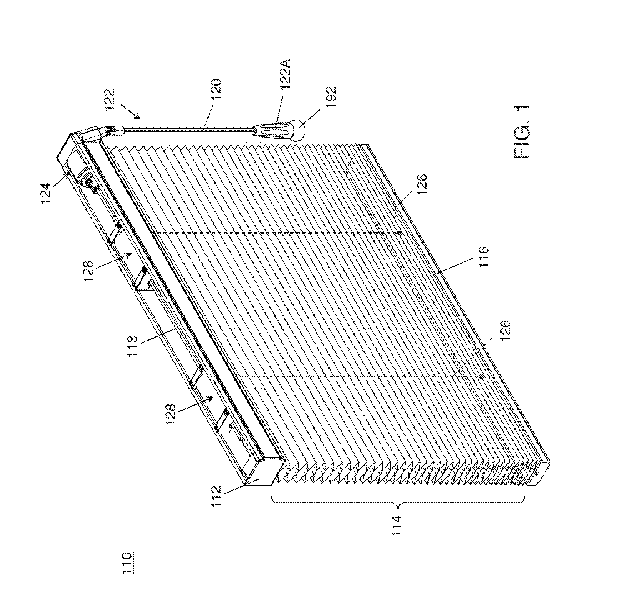
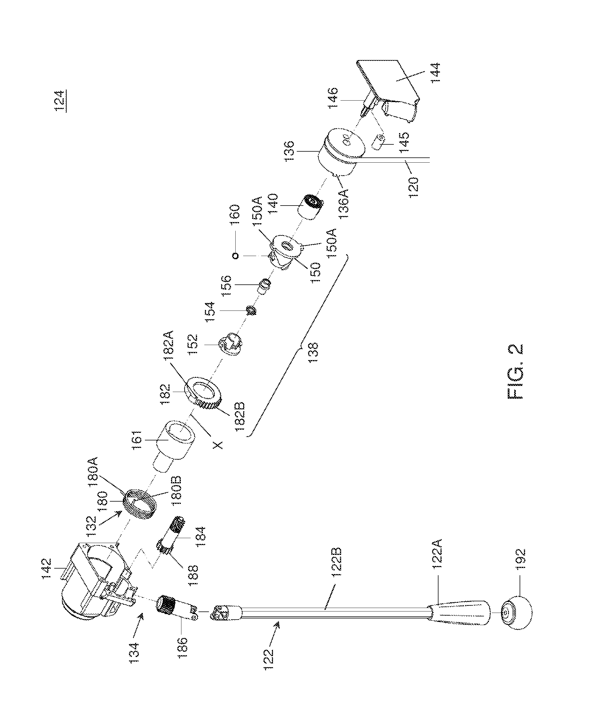
[0048]FIG. 1 is a perspective view illustrating an embodiment of a window shade 110. The window shade 110 can include a head rail 112, a shading structure 114, and a bottom part 116 disposed at the bottom of the shading structure 114. For operatively actuating the shading structure 114 and the bottom part 116, the window shade 110 can include a control module 124, a plurality of suspension cords 126 (shown with phantom lines), and a plurality of cord winding units 128. The control module 124 can include a drive axle 118, an operating cord 120 (shown with phantom line) and an actuator 122. Each suspension cord 126 can be assembled between the head rail 112 and the bottom part 116, a first end portion of the suspension cord 126 being connected with a rotary drum of one associated winding unit 128, and a second end portion of the suspension cord 126 being connected with the bottom part 116. The shading structure 114 can be gathered upward by raising the bottom part 116 toward the head ...


PUM


Abstract

A window shade comprises a head rail, a shading structure, a bottom part, suspension cords connected with cord winding units, and a control module. The control module includes a drive axle assembled with the cord winding units, a sleeve affixed with the drive axle, an arrester assembled around the drive axle, and a release unit. The arrester has a locking state in which the arrester blocks a rotational displacement of the sleeve and the drive axle to keep the bottom part at a desired position, and an unlocking state in which rotation of the sleeve and the drive axle is allowed to lower the bottom part by gravity action. The release unit includes an actuator that is operatively connected with the arrester and has an elongated shape. The actuator can rotate about its lengthwise axis to turn the arrester from the locking to unlocking state.

Description

CROSS-REFERENCE TO RELATED APPLICATION(S)[0001]This application claims priority to Taiwan Patent Application No. 101106084 filed on Feb. 23, 2012.BACKGROUND[0002]1. Field of the Invention[0003]The present inventions relate to window shades, and control modules used for actuating window shades.[0004]2. Description of the Related Art[0005]Many types of window shades are currently available on the market, such as Venetian blinds, roller shades and honeycomb shades. The shade when lowered can cover the area of the window frame, which can reduce the amount of light entering the room through the window and provided increased privacy. Conventionally, the window shade is provided with an operating cord that can be actuated to raise or lower the window shade. In particular, the operating cord may be pulled downward to raise the window shade, and released to lower the window shade.[0006]In a conventional construction of the window shade, the operating cord can be connected with a drive axle. ...

Claims


Application Information

Patent Timeline
Patent Type & Authority Applications(United States)
IPC IPC(8): A47H5/02
CPCE06B9/30E06B9/322E06B9/42E06B9/50E06B2009/905E06B9/90E06B2009/2627E06B2009/3222E06B9/78E06B9/32E06B9/262E06B9/307E06B9/308E06B9/323
Inventor YU, FU-LAIHUANG, CHIN-TIEN
Owner TEH YOR CO LTD
Why Eureka
Try Eureka