Power Transmission Systems and Components For Direct Current Applications

Inactive Publication Date: 2013-08-29
ADVANCED MAGNET LAB
View PDF4 Cites 6 Cited by
  • Summary
  • Abstract
  • Description
  • Claims
  • Application Information

AI Technical Summary

Benefits of technology

[0014]According to one series of embodiments there is provided a power conversion and distribution system. A motor is positioned to convert a high voltage power signal to mechanic

Problems solved by technology

Transmission associated with electric power generation and consumption typically requires a series of power conversion steps which add to the cost and reduce the efficiencies of operations.
Nonetheless, even with economies of scale, there have been limited means for improving the efficiency of power delivery.
A typical data center may occupy ten to one hundred thousand square feet and consume megawatts of power.
It has been estimated that data centers in the United States presently consume approximately three percent of all electric power generated in the United

Method used


Image

  • Power Transmission Systems and Components For Direct Current Applications
  • Power Transmission Systems and Components For Direct Current Applications
  • Power Transmission Systems and Components For Direct Current Applications

Examples


Embodiment Construction

[0032]Before describing in detail exemplary systems and methods relating to the invention, it should be observed that the present invention resides primarily in a novel and non-obvious combination of elements and method steps. So as not to obscure the disclosure with details that will be readily apparent to those skilled in the art, certain conventional elements and steps have been presented with lesser detail, while the drawings and the specification describe in greater detail other elements and steps pertinent to understanding the invention. Also, the following embodiments are exemplary constructions which do not define limits as to structural arrangements or methods according to the invention. The embodiments are permissive rather than mandatory and are illustrative rather than exhaustive.

1. AC-DC and DC-DC Conversion With Built-In Energy Storage

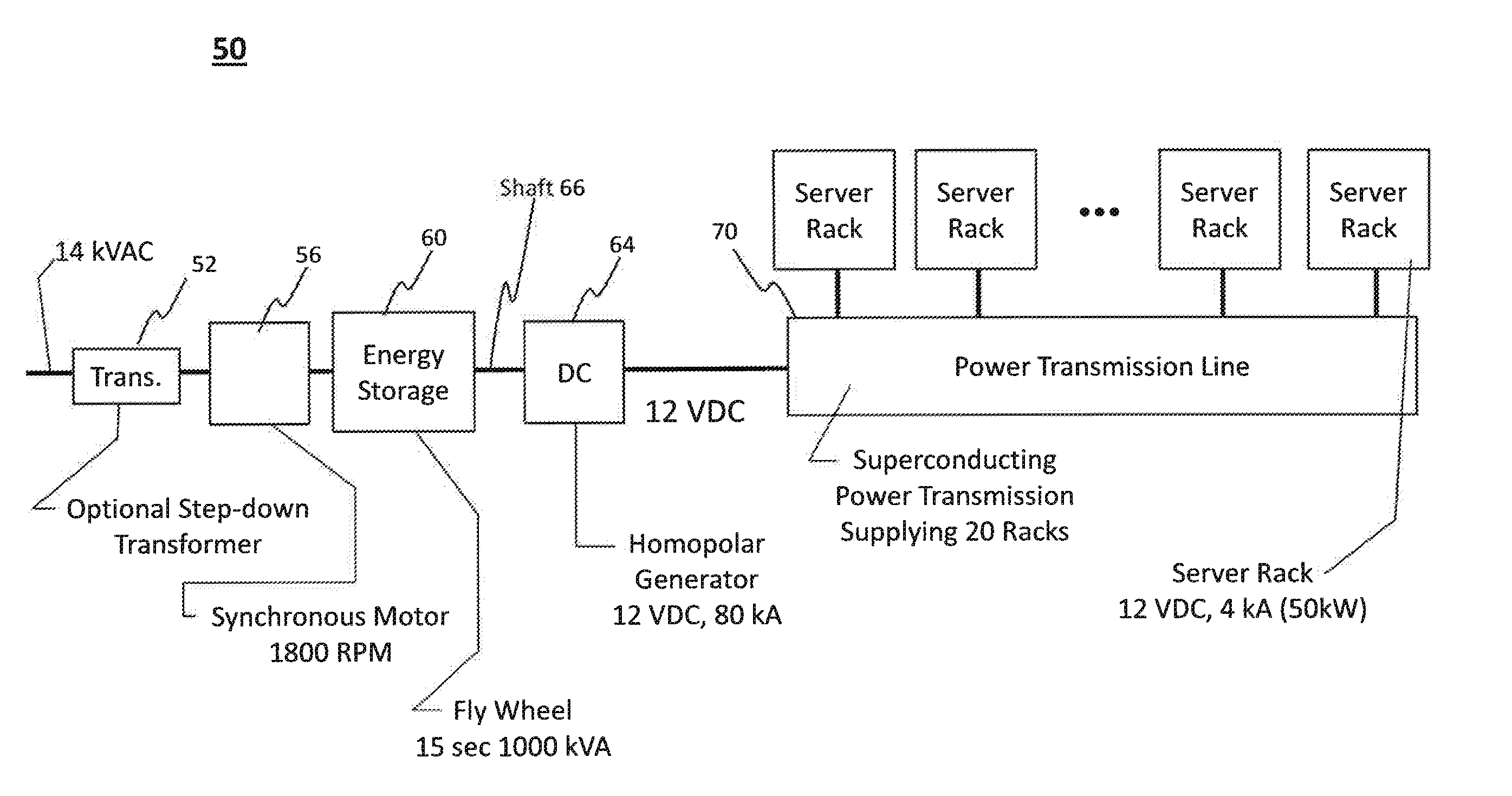
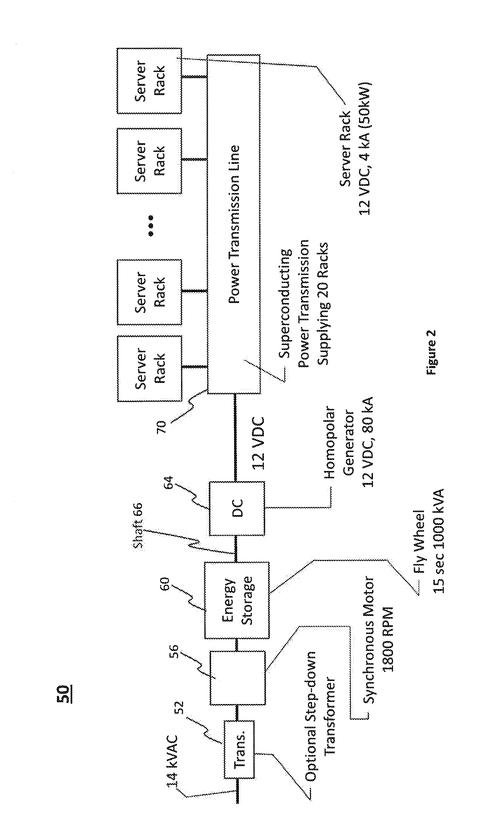
[0033]FIG. 2 illustrates a power distribution system 50 according to an embodiment of the invention. In lieu of incorporating multiple c...


PUM


Abstract

A power conversion and distribution system. In one embodiment low voltage source components convert a high voltage AC power source to a relatively low voltage supply and provide a direct current output. First superconductor wires carry current from the low voltage source components to a load, and second superconductor wires carry current from the load to the low voltage source components. Individual ones of the first wires are grouped with individual ones of the second wires so that wires connected to carry current in opposite directions are in such sufficiently close proximity that additives of self-fields generated by individual ones of the wires during power transmission result in reduction of the magnetic fringe field generated, thereby increasing the current carrying capacity of the wires.

Description

PRIORITY BASED ON RELATED APPLICATION[0001]This application claims priority based on International Patent Application PCT / US2011 / 55178 filed Oct. 6, 2011 and U.S. Provisional Application No. 61 / 390,787 filed Oct. 7, 2010.FIELD OF THE INVENTION[0002]The present invention relates to electrical systems and associated methods of operation, including systems for transmitting electric power. More particularly, embodiments of the present invention relate to power conversion and distribution systems, including homopolar generator systems, and transmission line circuitry for conducting power from a source to a load.BACKGROUND[0003]Transmission associated with electric power generation and consumption typically requires a series of power conversion steps which add to the cost and reduce the efficiencies of operations. The conventional transmission path typically includes a high voltage alternating current (AC) segment, typically on the order of 14 KV, followed by one or more voltage reduction...

Claims


Application Information

Patent Timeline
IPC IPC(8): H02J3/00
CPCH02K55/00H01R3/00H02K13/00H02J2001/002Y02E40/62H02J1/00H02K47/04H02K47/14H02K7/1838H02J3/00H02J1/002Y02E40/60
Inventor MEINKE, RAINERISHMAEL, SASHA
Owner ADVANCED MAGNET LAB
Why Eureka
Try Eureka