Dental treating apparatus

a technology for treating equipment and teeth, applied in dental tools, dental surgery, medical science, etc., can solve the problems of excessive load not being applied to the cutting tool, tooth itself must be drawn, cutting tool breakage, etc., to achieve safe cutting and prevent cutting. , the effect of cutting tool breakag

Active Publication Date: 2013-08-29
MORITA MFG CO LTD
View PDF20 Cites 25 Cited by
  • Summary
  • Abstract
  • Description
  • Claims
  • Application Information

AI Technical Summary

Benefits of technology

[0013]The present invention provides a dental treating apparatus in which breakage of a cutting tool and excessive

Problems solved by technology

However, application of excessive load results in breakage of the cutting tool.
Therefore, the cutting tool of the dental treating apparatus must be driven such that the excessive load is not applied to the cutting tool.
Furthermore, if the cutting tool cannot be removed from the root canal, the tooth itself must be draw

Method used


Image

  • Dental treating apparatus
  • Dental treating apparatus
  • Dental treating apparatus

Examples


first embodiment

[0031]A dental treating apparatus according to a first embodiment of the present invention is a root canal treating device including a root canal enlarging and root canal length measuring system into which a dental hand piece for treatment on a root canal is incorporated. The dental treating apparatus according to the present invention is, however, not limited to the root canal treating device, and can be applied to a dental treating apparatus with a similar configuration.

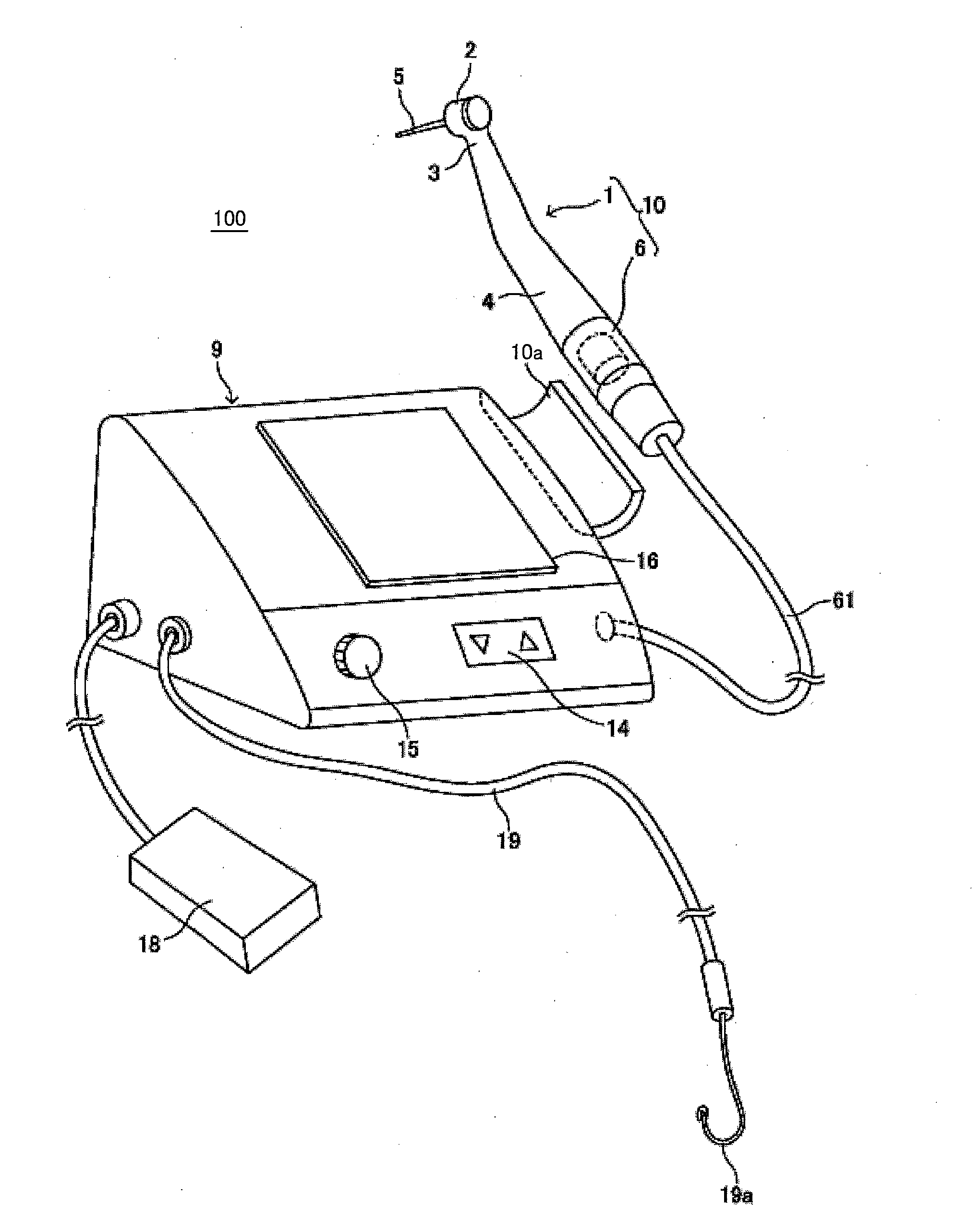
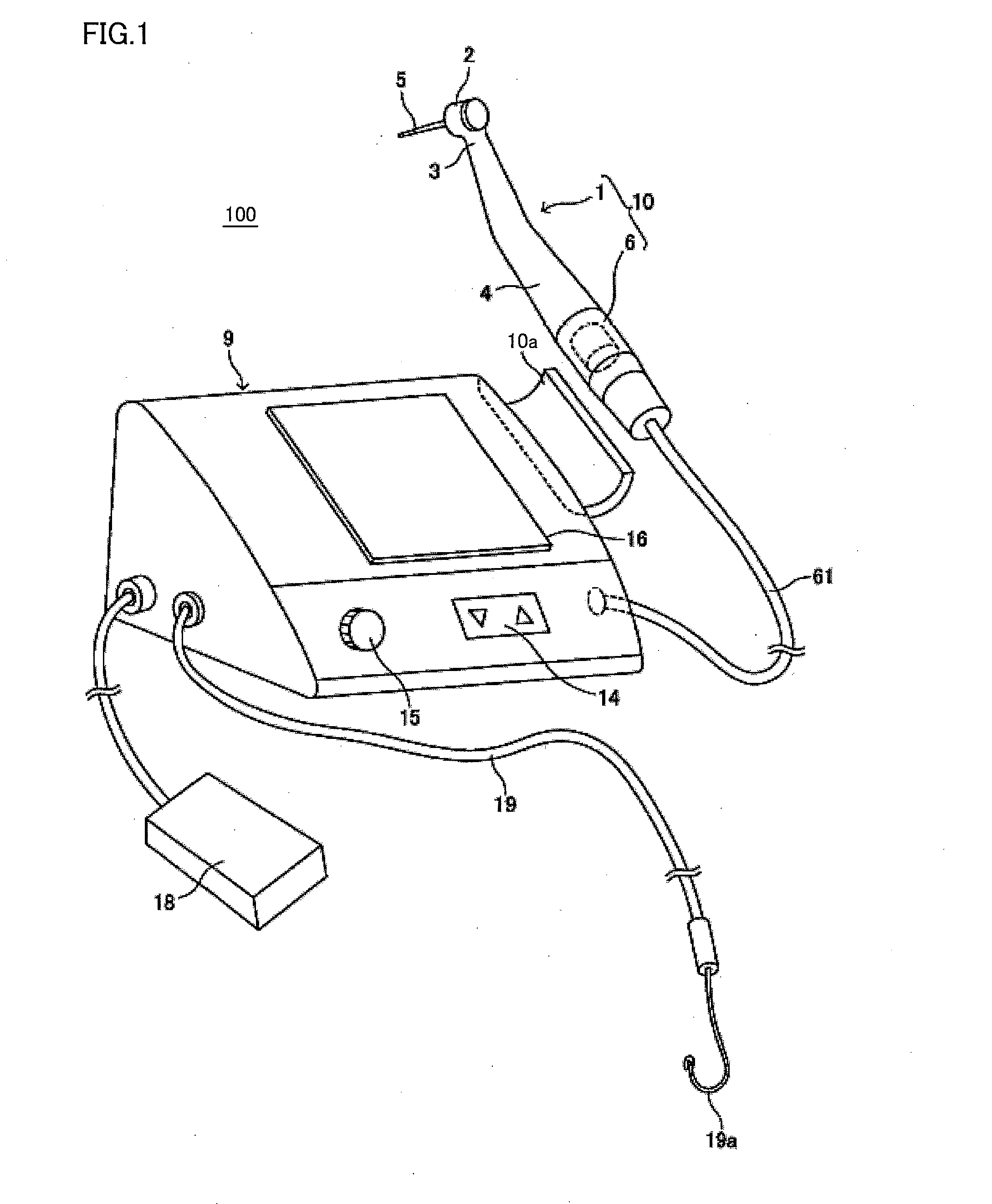
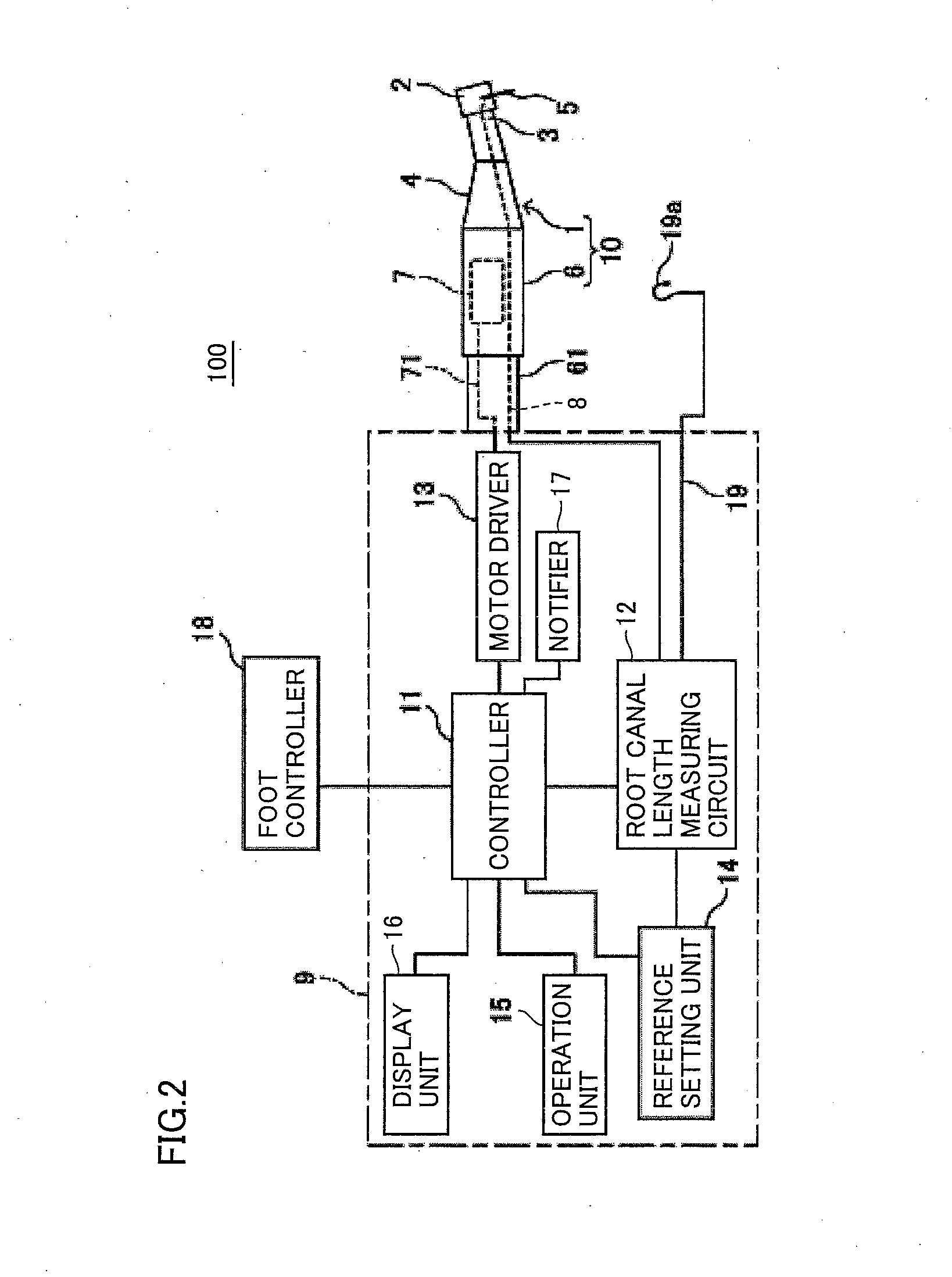
[0032]FIG. 1 is a schematic diagram showing an appearance of a configuration of the root canal treating device according to the first embodiment of the present invention. FIG. 2 is a block diagram showing a configuration of functions of the root canal treating device according to the first embodiment of the present invention. A root canal treating device 100 as shown in FIG. 1 includes a hand piece 1, a motor unit 6 and a control box 9 for treating dental root canal.

[0033]Hand piece 1 for treating the dental root c...

second embodiment

[0105]In the first embodiment, description has been given to root canal treating device 100 in which at least one parameter of the normal rotation angle, the number of normal rotations, the reverse rotation angle, and the number of reverse rotations is changed in accordance with the load applied to cutting tool 5, which is detected by resistor 13d for load detection. However, the driving state of the cutting tool that is referred to for the purpose of changing the parameters such as the normal rotation angle is not limited to the load applied to cutting tool 5 but may be a position of the tip end of cutting tool 5 in the root canal (hereinafter also simply referred to as the position of cutting tool 5) that is obtained by root canal length measuring circuit 12. In a root canal treating device according to a second embodiment, at least one parameter of the normal rotation angle, the number of normal rotations, the reverse rotation angle, and the number of reverse rotations is changed...

third embodiment

[0120]A combination of the load applied to cutting tool 5 and the position of cutting tool 5 may be used as the driving state of the cutting tool that is referred to for the purpose of changing the parameters such as the normal rotation angle. In a root canal treating device according to a third embodiment, at least one parameter of the normal rotation angle, the number of normal rotations, the reverse rotation angle, and the number of reverse rotations is changed in accordance with the load applied to cutting tool 5, which is detected by resistor 13d for load detection, and the position of cutting tool 5 obtained by root canal length measuring circuit 12.

[0121]Since the root canal treating device according to the third embodiment has the same configuration as that of root canal treating device 100 according to the first embodiment shown in FIGS. 1 to 3, the same reference characters are assigned and detailed description will not be repeated.

[0122]Next, description is given to drivi...


PUM


Abstract

The present invention is directed to a dental treating apparatus including: a hand piece; a power source (micro motor); a driving unit (motor driver); a driving state detecting unit (resistor for load detection, root canal length measuring circuit); and a controller. The hand piece drivably holds a cutting tool on a head unit. The power source drives the cutting tool. The driving unit drives the cutting tool with twist driving in which the normal rotation and the reverse rotation are repeated. The driving state detecting unit detects a driving state of the cutting tool. The controller changes at least one parameter of a rotation angle in the normal rotation, a rotation angle speed in the normal rotation, a rotation angle in the reverse rotation, and a rotation angle speed in the reverse rotation in accordance with the driving state of the cutting tool detected by the driving state detecting unit.

Description

BACKGROUND OF THE INVENTION[0001]1. Field of the Invention[0002]The present invention relates to a dental treating apparatus with a hand piece, more specifically, to a dental treating apparatus that causes a cutting tool for cutting and enlarging an inner wall of a root canal of a tooth to be driven.[0003]2. Description of the Background Art[0004]As for a dental treating apparatus with a hand piece, there is, for example, an apparatus for providing treatment by attaching a cutting tool to a head unit of a hand piece and driving the cutting tool to cut and enlarge a root canal of a tooth. U.S. Pat. No. 3,264,607 (PTL 1), U.S. Pat. No. 3,676,753 (PTL 2) and U.S. Pat. No. 3,615,209 (PTL 3) disclose various types of driving control in order to, for example, prevent breakage due to a load applied to the cutting tool when the dental treating apparatus causes the cutting tool to be driven to cut and enlarge the root canal of the tooth.[0005]A dental treating apparatus disclosed in PTL 1 in...

Claims


Application Information

Patent Timeline
IPC IPC(8): A61C1/00
CPCA61C1/003A61C19/042
Inventor YAMASHITA, SEIICHIROTOKUNAGA, KYOSHIKATSUDA, NAOKI
Owner MORITA MFG CO LTD
Why Eureka
Try Eureka