

Automatic lubrication system
a lubrication system and automatic technology, applied in the direction of manual lubrication, machines/engines, distribution equipment, etc., can solve the problems of reducing the longevity of industrial machines and their structures, increasing wear on these elements, and reducing pin li
- Summary
- Abstract
- Description
- Claims
- Application Information
AI Technical Summary
Benefits of technology
Problems solved by technology
Method used
Image

Examples
Embodiment Construction
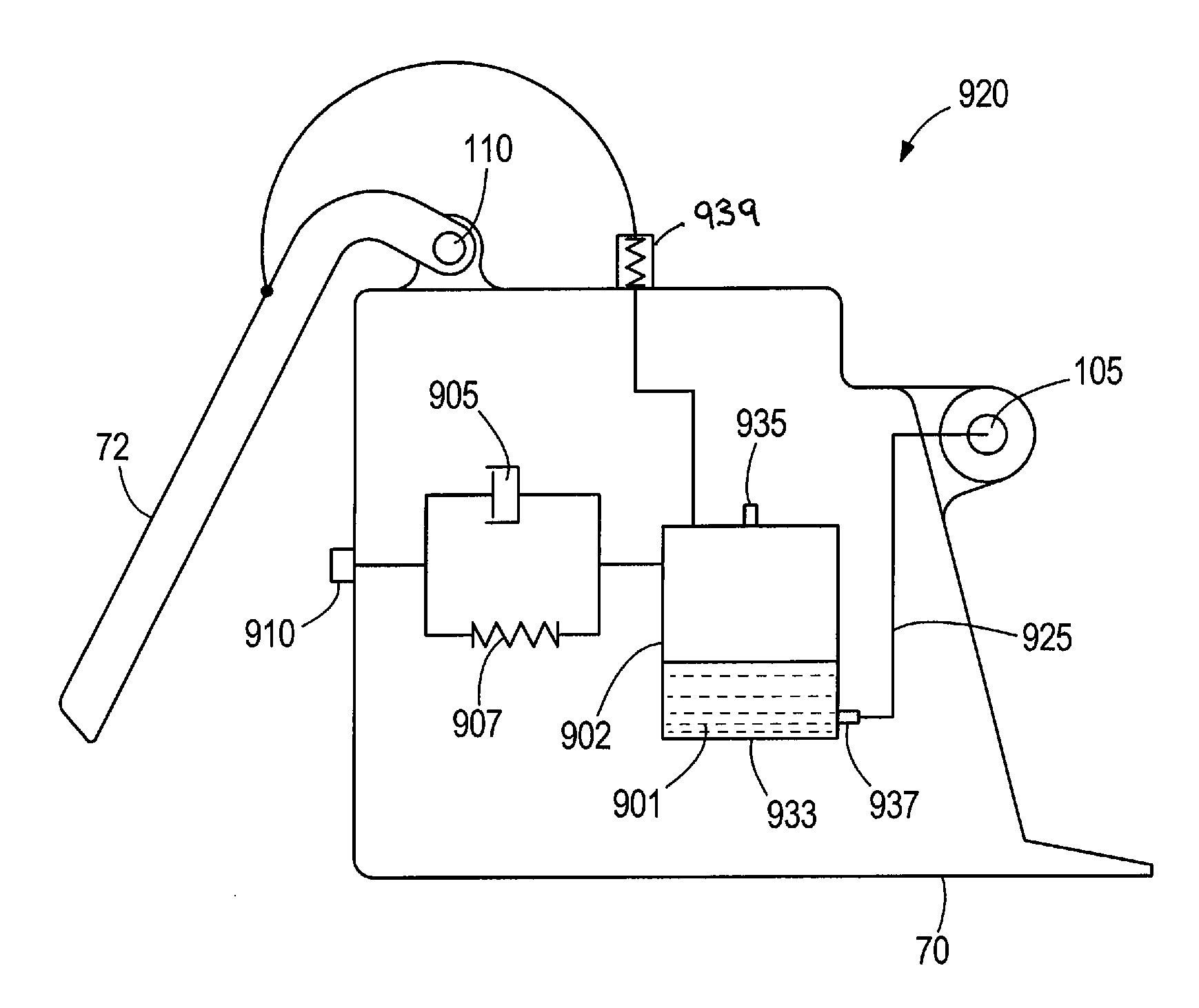
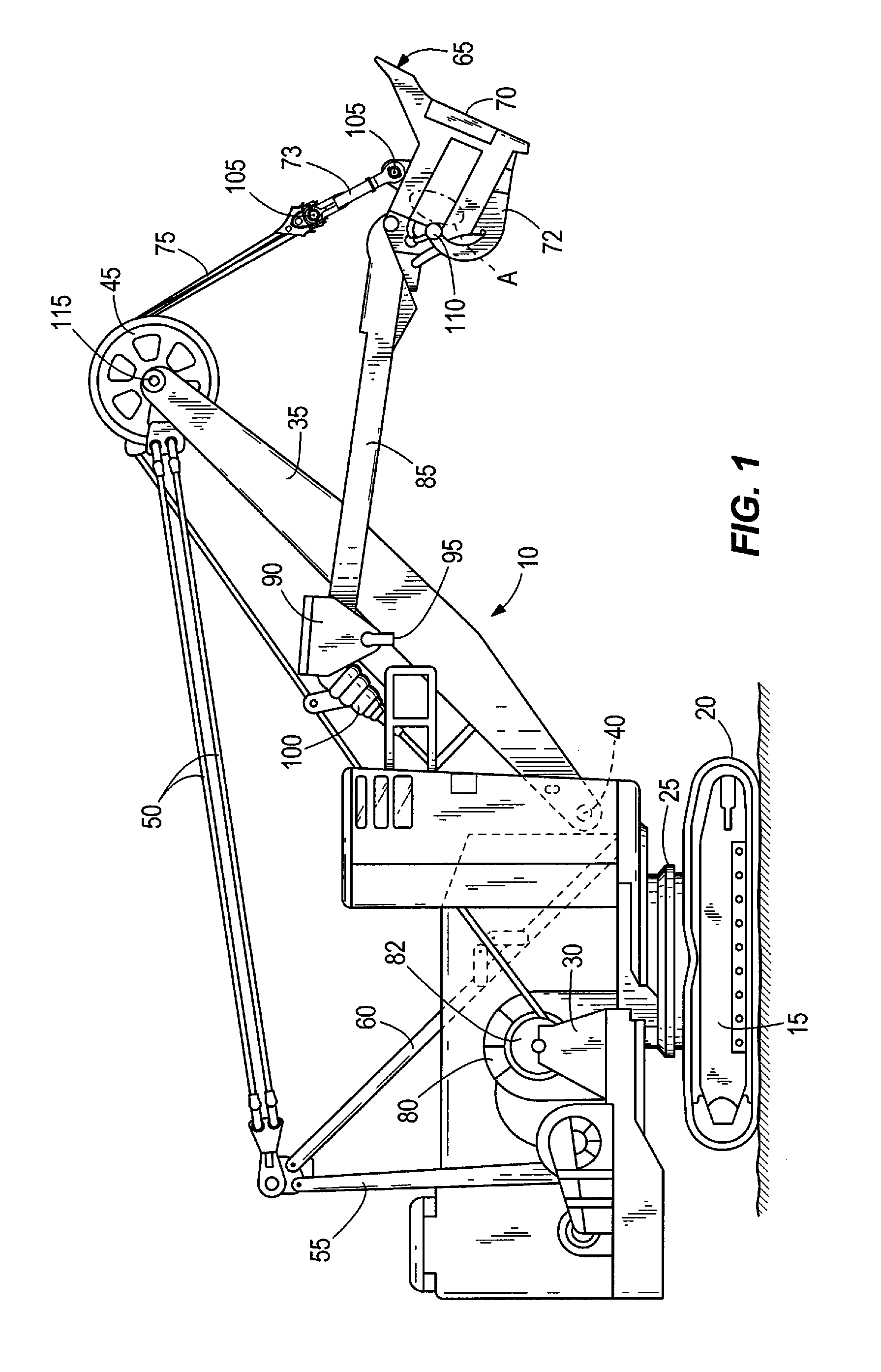
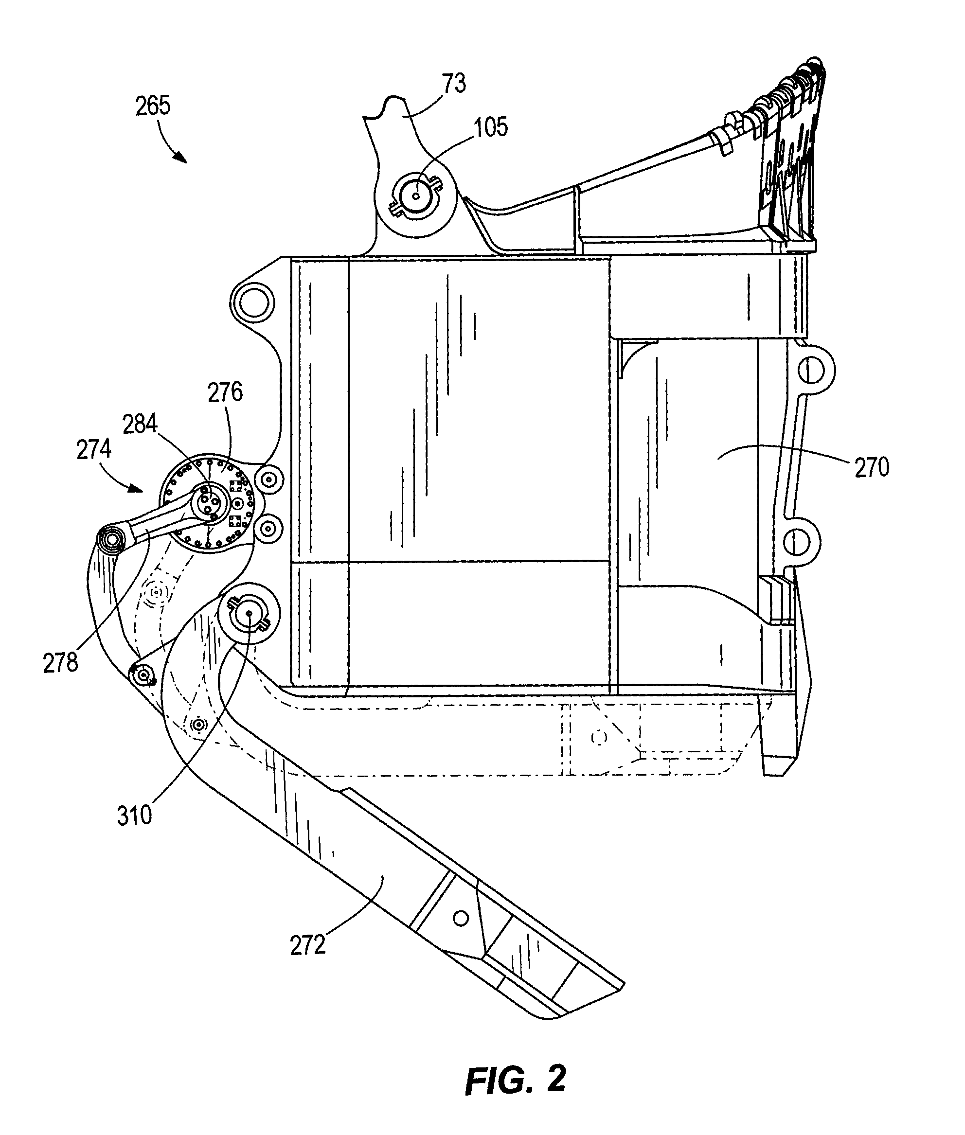
[0018]FIGS. 1-7 illustrate various structural elements that benefit from the automatic lubrication systems described herein. While a shovel and dippers are illustrated, the automatic lubrication systems described herein are applicable to a variety of different industrial machines and industrial machine mechanical components.
[0019]FIG. 1 illustrates a mining shovel 10 that includes a mobile base 15, drive tracks 20, a turntable 25, a revolving frame 30, a boom 35, a lower end 40 (also called a boom foot), tension cables 50, a gantry tension member 55, a gantry compression member 60, a dipper 65 including a dipper body 70 and a dipper door 72, a bail 73, a hoist rope 75, a winch drum 80, an electric motor 82, a dipper handle 85, a saddle block 90, a pivot point 95 (e.g., a shipper shaft), a transmission unit 100 (also called a crowd drive), a bail pin 105, a dipper door pin 110, and a boom point pin 115.
[0020]The mobile base 15 is supported by the drive tracks 20. The mobile base 15 s...
PUM
 Abstract
Description
Claims
Application Information