Apparatus and method for deriving a directional information and computer program product

a technology of directional information and computer program product, applied in the direction of electrical transducers, transducer details, electrical apparatus, etc., can solve the problems of reducing the microphone spacing d, aliasing, and affecting the estimation of directional parameters such as the diffuseness of a sound field

Active Publication Date: 2013-09-05
FRAUNHOFER GESELLSCHAFT ZUR FOERDERUNG DER ANGEWANDTEN FORSCHUNG EV
View PDF5 Cites 13 Cited by
  • Summary
  • Abstract
  • Description
  • Claims
  • Application Information

AI Technical Summary

Benefits of technology

[0021]According to some embodiments, an effective microphone look direction associated to a microphone signal describes the direction where the microphone from which the microphone signal is derived has its maximum response (or its highest sensitivity). As an example, the microphone may be a directional microphone possessing a non isotropic pick up pattern and the effective microphone look direction can be defined as the direction where the pick up pattern of the microphone has its maximum. Hence, for a directional microphone the effective microphone look direction may be equal to the microphone look direction (describing the direction towards which the directional microphone has a maximum sensitivity), e.g. when no objects modifying the pick-up pattern of the directional microphone are placed near the microphone. The effective microphone look direction may be different to the microphone look direction of the directional microphone if the directional microphone is placed near an object that has the effect of modifying its pick-up pattern. In this case the effective microphone look direction may describe the direction, where the directional microphone has its maximum response.
[0022]In the case of an omnidirectional microphone, an effective response pattern of the omnidirectional microphone may be shaped, for example, using a shadowing object (which has an effect of the effect of modifying the pick-up pattern of the microphone), such that the shaped effective response pattern has an effective microphone look direction which is the direction of maximum response of the omnidirectional microphone with the shaped effective response pattern.

Problems solved by technology

However, these approaches make use of the phase information of the microphone signals, leading inevitably to spatial aliasing.
Additionally, the estimation of directional parameters such as diffuseness of a sound field are also affected.
Notice that reducing the microphone spacing d, which increases the spatial aliasing limit fmax, is not a feasible solution for most applications, as a too small d significantly reduces the estimation reliability at low frequencies in practice.
It has been found that the problem of spatial aliasing in directional parameter estimation results from ambiguities in the phase information within the microphone signals.

Method used


Image

  • Apparatus and method for deriving a directional information and computer program product
  • Apparatus and method for deriving a directional information and computer program product
  • Apparatus and method for deriving a directional information and computer program product

Examples


Embodiment Construction

5.1 Apparatus According to FIG. 1

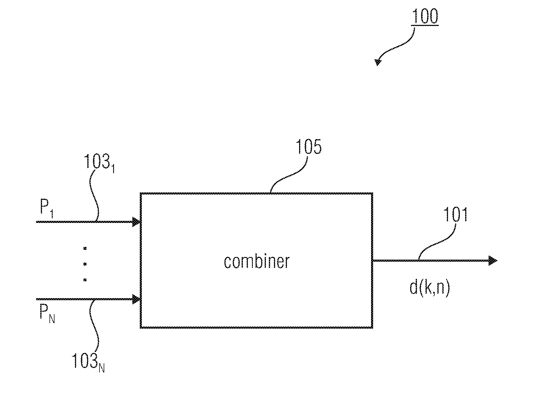
[0047]FIG. 1 shows an apparatus 100 according to an embodiment of the present invention. The apparatus 100 for deriving a directional information 101 (also denoted as d(k, n)) from a plurality of microphone signals 1031 to 103N (also denoted as P1 to PN) or from a plurality of components of a microphone signal comprises a combiner 105. The combiner 105 is configured to obtain a magnitude value from a microphone signal or a component of the microphone signal, and to linearly combine direction information items describing effective microphone look directions being associated with the microphone signals 1031 to 103N or the components, such that a direction information item describing a given effective microphone look direction is weighted in dependence on the magnitude value of the microphone signal, or of the component of the microphone signal, associated with the given effective microphone look direction to derive the directional information 101.

[0048...


PUM


Abstract

An apparatus for deriving a directional information from a plurality of microphone signals or from a plurality of components of a microphone signal, wherein different effective microphone look directions are associated with the microphone signals or components, has a combiner configured to obtain a magnitude value from a microphone signal or a component of the microphone signal. The combiner is further configured to combine direction information items describing the effective microphone look directions, such that a direction information item describing a given effective microphone look direction is weighted in dependence on the magnitude value of the microphone signal, or of the component of the microphone signal, associated with the given effective microphone look direction, to derive the directional information.

Description

CROSS-REFERENCE TO RELATED APPLICATIONS[0001]This application is a continuation of copending International Application No. PCT / EP2011 / 068805, filed Oct. 28, 2010, which is incorporated herein by reference in its entirety, and additionally claims priority from U.S. Application No. 61 / 407,574, filed Oct. 28, 2010 and European Application Number EP 11 166 916.4, filed May 20, 2011, all of which are incorporated herein by reference in their entirety.BACKGROUND OF THE INVENTION[0002]Embodiments of the present invention relate to an apparatus for deriving a directional information from a plurality of microphone signals or from a plurality of components of a microphone signal. Further embodiments relate to systems comprising such an apparatus. Further embodiments relate to a method for deriving a directional information from a plurality of microphone signals.[0003]Spatial sound recording aims at capturing a sound field with multiple microphones such that at the reproduction side, a listene...

Claims


Application Information

Patent Timeline
Patent Type & Authority Applications(United States)
IPC IPC(8): H04R3/00
CPCH04R3/005H04S2420/05H04S2400/15H04R3/00
Inventor KUECH, FABIANDEL GALDO, GIOVANNITHIERGART, OLIVERPULKKI, VILLEAHONEN, JUKKA
Owner FRAUNHOFER GESELLSCHAFT ZUR FOERDERUNG DER ANGEWANDTEN FORSCHUNG EV
Why Eureka
Try Eureka