Method and device for uniformly treating adherent cells

a technology of adherent cells and uniform treatment, which is applied in the field of can solve the problems of high mortality, unfavorable large leakage of cell free culture medium above the cells, so as to achieve efficient and uniform treatment of adherent cells, the effect of minimal strength

Active Publication Date: 2013-09-05
LONZA COLOGNE
View PDF1 Cites 2 Cited by
  • Summary
  • Abstract
  • Description
  • Claims
  • Application Information

AI Technical Summary

Benefits of technology

[0010]According to the invention, the object is achieved by a method of the initially mentioned kind, in which at least two electrodes are active electrodes when the voltage is applied for generating a first electric field, and at least a second electric field is generated, wherein at least one of the two former active electrodes is a floating electrode when the voltage is applied. If, for example, a first electrode is active, i.e. either positive or negative pole, when a voltage pulse are applied to the cells, the electric field underneath this electrode has minimum strength so that the cells orthogonally located underneath this electrode are not sufficiently electrically treated. Consequently, according to the invention a second electric field is generated wherein said first electrode is now floating (passive). That is, the e

Problems solved by technology

A significant disadvantage of this arrangement is that a major part of the current leaks in the cell free culture medium above the cells.
But this field is only effective at the border area on the bottom of the container, where the cells are located, so that unnecessary high currents have to be provided.
Moreover, high mortality has to be assumed because of pH-value ch

Method used


Image

  • Method and device for uniformly treating adherent cells
  • Method and device for uniformly treating adherent cells
  • Method and device for uniformly treating adherent cells

Examples


Embodiment Construction

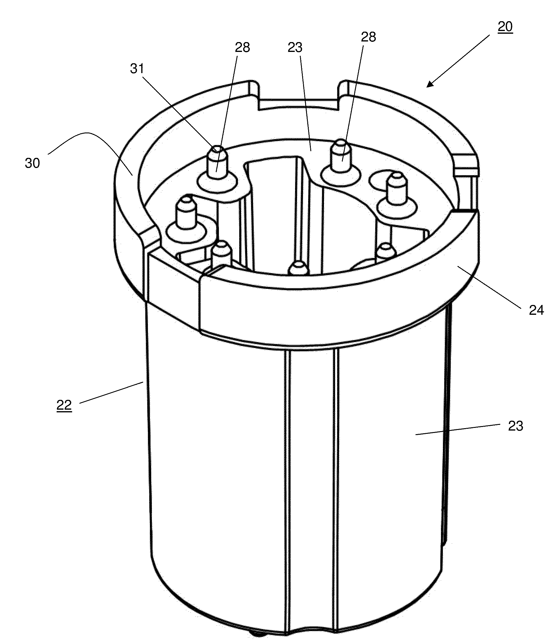
[0009]It is the object of the invention to provide a method and device enabling an efficient and uniform treatment of adherent cells using an electric field.

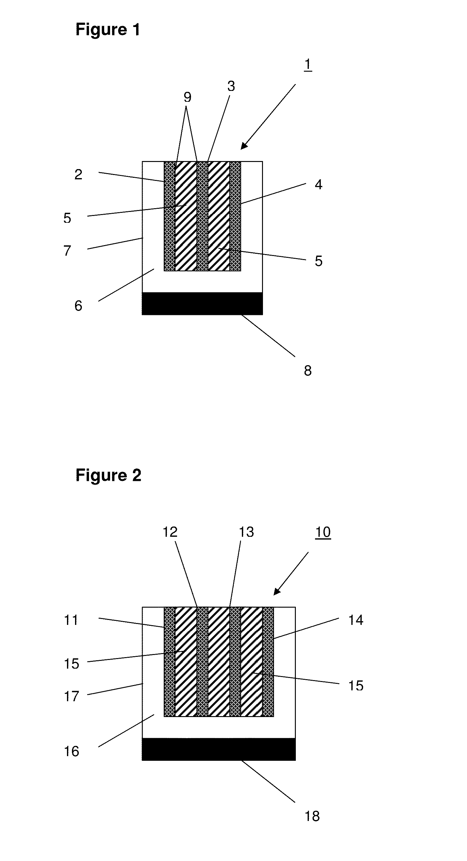
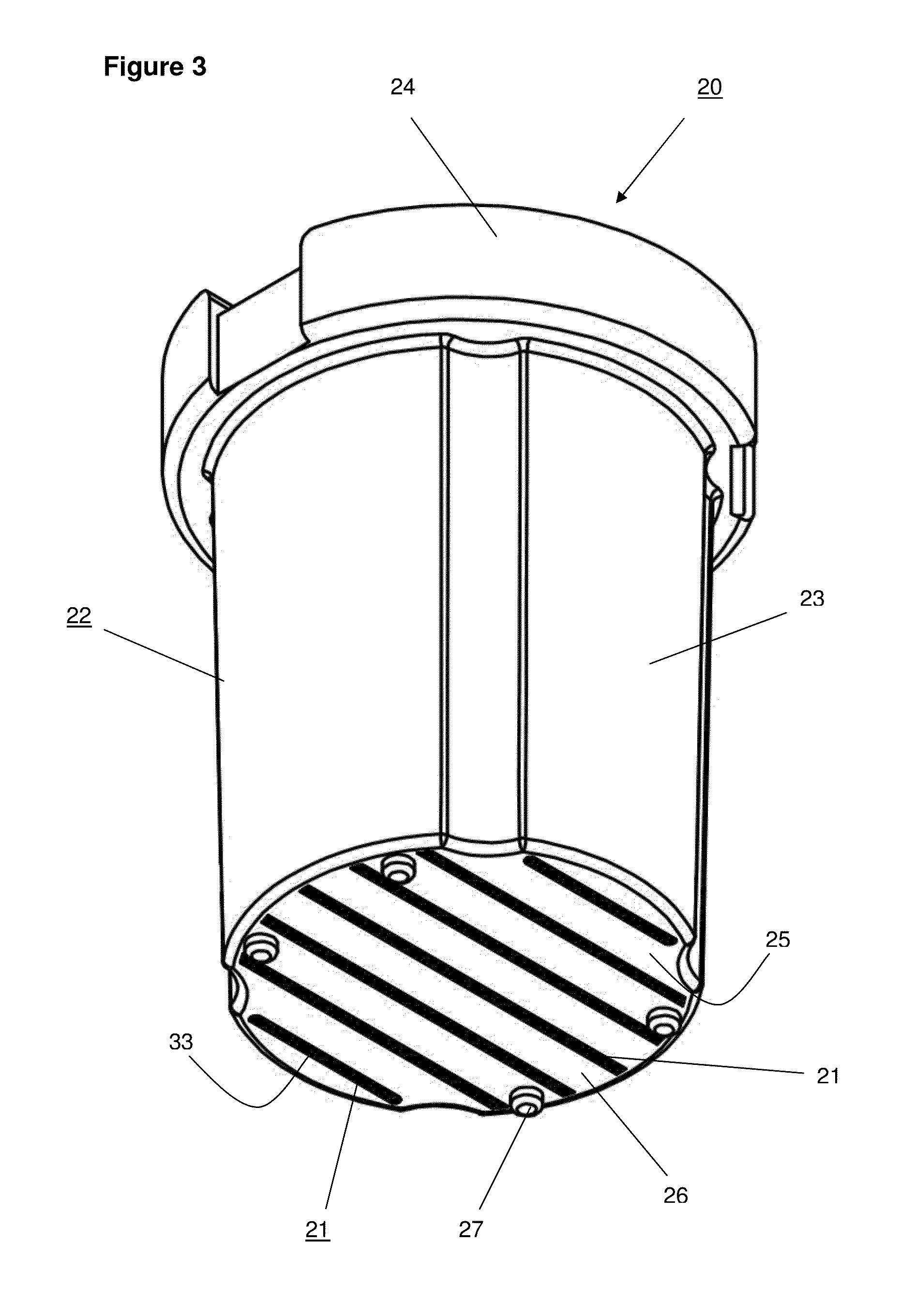
[0010]According to the invention, the object is achieved by a method of the initially mentioned kind, in which at least two electrodes are active electrodes when the voltage is applied for generating a first electric field, and at least a second electric field is generated, wherein at least one of the two former active electrodes is a floating electrode when the voltage is applied. If, for example, a first electrode is active, i.e. either positive or negative pole, when a voltage pulse are applied to the cells, the electric field underneath this electrode has minimum strength so that the cells orthogonally located underneath this electrode are not sufficiently electrically treated. Consequently, according to the invention a second electric field is generated wherein said first electrode is now floating (passive). That is, the el...


PUM


Abstract

The invention relates to a method for subjecting adherent cells to at least one electric field, in which the electric field is generated by applying a voltage to at least two active electrodes 63, wherein at least three electrodes 63, 64 are provided, and wherein at least two electrodes 63, 64 are active electrodes 63 when the voltage is applied in order to generate a first electric field, and in which at least one second electric field is generated, wherein at least one of the two previously active electrodes 63 is a potential-free electrode 64 when the voltage is applied. The invention further relates to a device 58 comprising at least three electrodes 63, 64, which are connected to at least one voltage source by means of at least one switching device 59, 60, 61, 62, wherein at least five electrodes 63, 64 are connected to the at least one voltage source by means of four switching devices 59, 60, 61, 62, wherein at least two electrodes 63, 64 are connected to the voltage source by means of a common switching device 59, 60, 61, 62. In conjunction with the method described above, the device according to the invention allows the efficient and uniform treatment of adherent cells using an electric field, wherein the switch between active and potential-free electrodes can be carried out quickly and safely using a lower number of switching devices.

Description

BACKGROUND OF THE INVENTION[0001]The invention relates to a method for applying at least one electric field to adherent cells, in which the electric field is generated by applying a voltage to at least two active electrodes, wherein at least three electrodes are provided. The invention further relates to a device comprising at least three electrodes which are connected to at least one voltage source via at least one switching device. The invention also relates to a device for contacting at least two electrode arrangements which each comprise at least two electrodes, wherein at least two electrode arrangements have different dimensions and wherein the device includes contact elements by means of which an electrical contact can be made to the electrodes of the electrode arrangements.PRIOR ART [0002]Application of an electric field or voltage pulse to living cells, so called electroporation or electrotransfection, is practiced for years on cells in various states. As single cells in su...

Claims


Application Information

Patent Timeline
IPC IPC(8): C12N13/00
CPCA61N1/327C12M23/12C12N15/87C12N13/00C12M35/02C12M1/42C12M3/00
Inventor KOBLIZEK, THOMASHEINZE, ANDREASGLEISSNER, TIMOMUELLER-HARTMANN, HERBERTWIRTH, ANDREAS
Owner LONZA COLOGNE
Why Eureka
Try Eureka