
Ultrasound imaging system and method with automatic adjustment and/or multiple sample volumes

a technology of ultrasonic imaging and multiple sample volumes, applied in ultrasonic/sonic/infrasonic image/data processing, ultrasonic/sonic image/data processing, applications, etc., can solve the problems of reducing the ability to view high flow rates, difficult to maintain the sample volume in a desired location, etc. achieve the effect of high pulse repetition frequency and facilitate the maintenance of the sample volum

Active Publication Date: 2013-09-05
FUJIFILM SONOSITE
View PDF2 Cites 2 Cited by
  • Summary
  • Abstract
  • Description
  • Claims
  • Application Information

AI Technical Summary

Benefits of technology

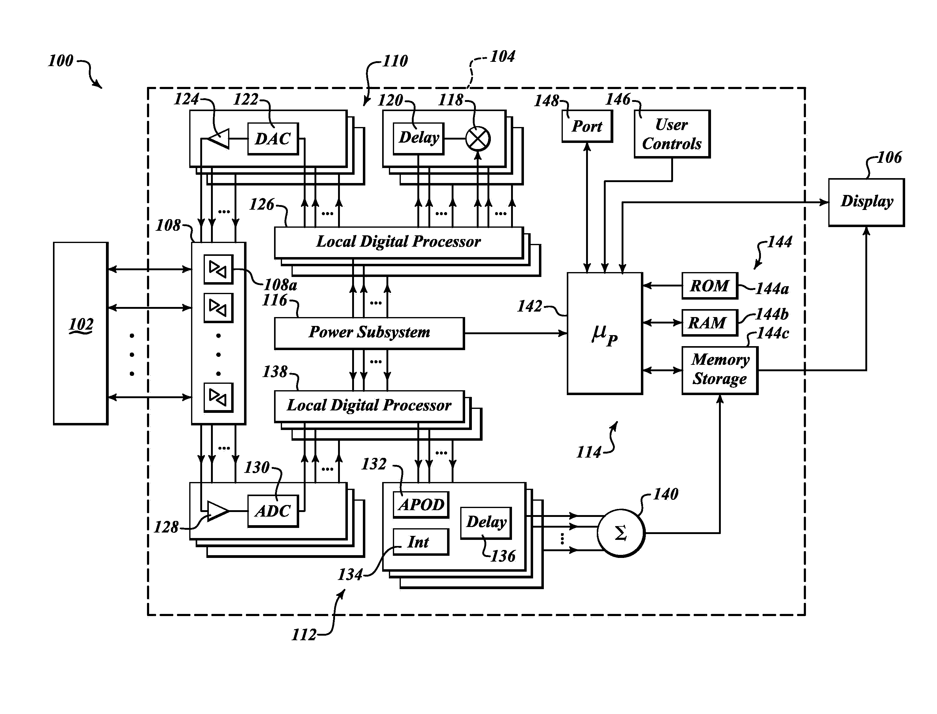
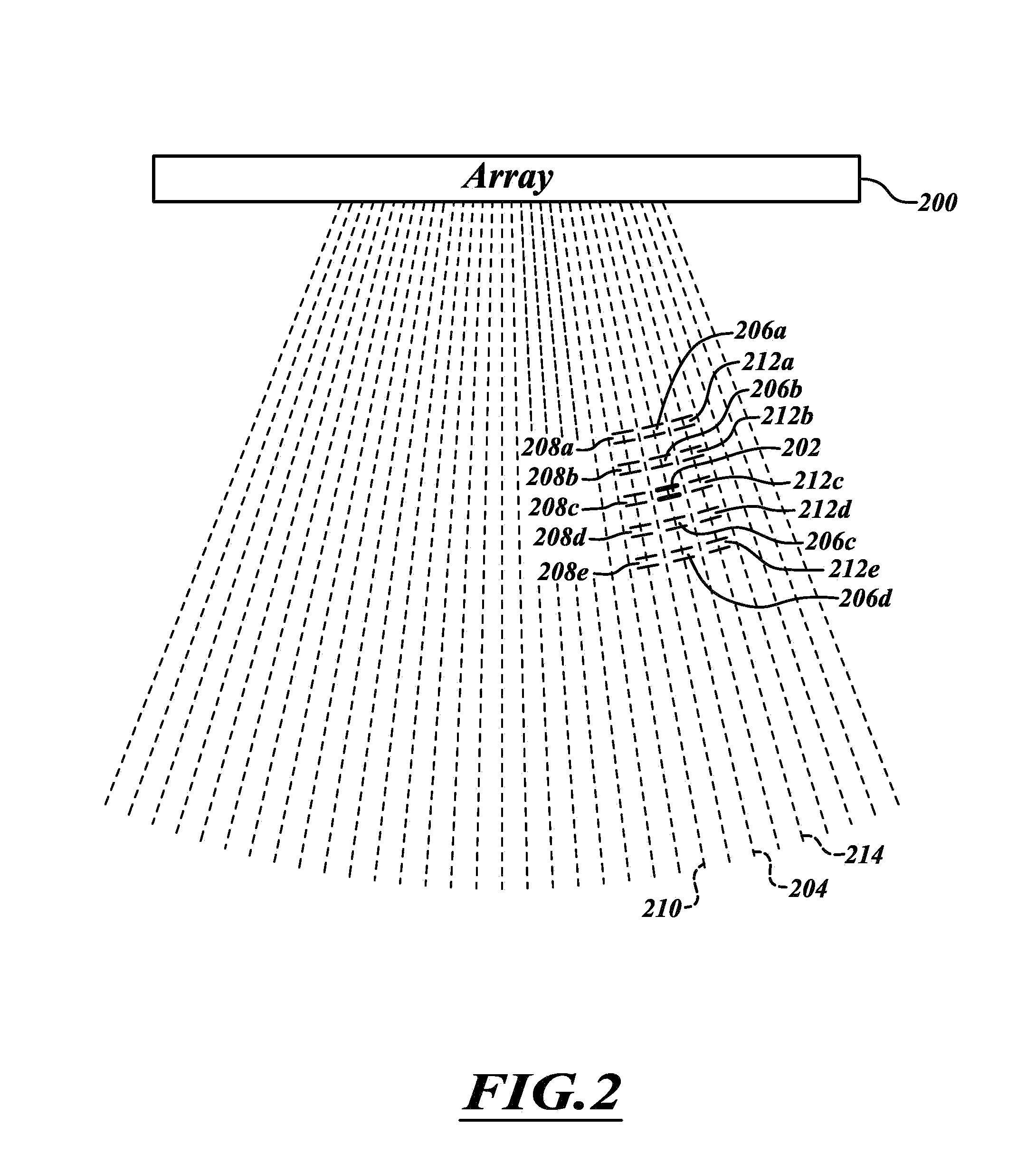
[0010]Systems and methods described herein adjust operation of an ultrasound imaging system based at least in part on one or more characteristics represented in ultrasound return signals from two or more sample volumes. Such may maintain a sample volume focused at a desired location or region of interest, for example centered with respect to some anatomical structure such as an artery. Such may facilitate ultrasound imaging when there is no or little movement of the transducer relative to the anatomical structure or when there is significant relative movement therebetween.

Problems solved by technology

However, it can be difficult to maintain the sample volume in a desired location.
Such may be difficult when there is no or relatively little relative movement between the transducer array and the desired location.
Such may be even more difficult when there is relative movement between the transducer array and the desired location, for instance where the transducer array is translated along a tissue or structure such as along an artery.
However, such may adversely take away acquisition time form Doppler firings, which reduces the ability to view high flow rates.

Method used


Image

  • Ultrasound imaging system and method with automatic adjustment and/or multiple sample volumes
  • Ultrasound imaging system and method with automatic adjustment and/or multiple sample volumes
  • Ultrasound imaging system and method with automatic adjustment and/or multiple sample volumes

Examples


Embodiment Construction

[0042]In the following description, certain specific details are set forth in order to provide a thorough understanding of various disclosed embodiments. However, one skilled in the relevant art will recognize that embodiments may be practiced without one or more of these specific details, or with other methods, components, materials, etc. In other instances, well-known structures associated with ultrasound imaging systems, microprocessors, micro-controllers, application specific integrated circuits, transducers and displays have not been shown or described in detail to avoid unnecessarily obscuring descriptions of the embodiments.

[0043]Unless the context requires otherwise, throughout the specification and claims which follow, the word “comprise” and variations thereof, such as, “comprises” and “comprising” are to be construed in an open, inclusive sense, that is as “including, but not limited to.”

[0044]Reference throughout this specification to “one embodiment” or “an embodiment” ...


PUM


Abstract

Adjustment of operation of an ultrasound imaging system may be based at least in part on one or more characteristics represented in ultrasound return signals from two or more sample volumes. Adjustment may include adjusting a principal sample volume location or selecting a new principal sample volume. For example, a location of a principal sample volume may be adjusted or new principal sample volume selected so as to remain focused on an identified region of interest or to maintain the principal sample volume relative to some structure or reference. The principal sample volume may be maintained in the center or along a centerline of an artery or other structure, as the transducer array is moved along the artery or structure.

Description

BACKGROUND[0001]1. Technical Field[0002]This application relates to ultrasound imaging systems, for instance medical diagnostic ultrasound imaging systems and, in particular, to the use of information contained in ultrasound return signals to operate the ultrasound imaging system.[0003]2. Description of the Related Art[0004]Ultrasound imaging systems employ transducer arrays to produce and transmit ultrasound pressure waves into an object such as a body, tissue or other material. The transducer arrays also receive ultrasound return or echo signals and produce analog transducer element voltage signals which are induced at the transducer array by the received ultrasound return or echo signals.[0005]Many ultrasound imaging systems are capable of operating in various modes for sampling, processing and / or presenting ultrasound information in a variety of useful representations. For example, ultrasound systems may employ A-, B-, M-, Doppler, energy, power, Doppler amplitude or color angio...

Claims


Application Information

Patent Timeline
Patent Type & Authority Applications(United States)
IPC IPC(8): A61B8/08
CPCA61B8/483A61B8/0891A61B8/4488A61B8/56A61B8/469A61B8/54A61B8/463A61B8/06A61B8/08A61B8/13A61B8/4494A61B8/465A61B8/467A61B8/486A61B8/488A61B8/5207A61B34/20
Inventor DUFFY, THOMAS M.
Owner FUJIFILM SONOSITE
Learn More