Expandable vein ligator catheter and method of use

a vein ligator and expandable technology, applied in the field of expandable vein ligator catheter and method of use, can solve the problems of additional valvular failure, inability to close the valve, unsightly discoloration, swelling, etc., and achieve the effect of uniform and predictable shrinkage of the vein wall

Inactive Publication Date: 2006-05-09
TYCO HEALTHCARE GRP LP
View PDF84 Cites 185 Cited by
  • Summary
  • Abstract
  • Description
  • Claims
  • Application Information

AI Technical Summary

Benefits of technology

[0013]Briefly, and in general terms, the present invention provides an apparatus and method for applying energy along a generally circumferential band of a vein wall. The application of energy as such results in a more uniform and predictable shrinkage of the vein wall.
[0020]In another aspect of the invention, external compression is used to initially force the wall of the vein to collapse toward the catheter. The application of energy molds the vein to durably assume the collapsed state initially achieved mechanically by the external compression. A tourniquet can be used to externally compress or flatten the anatomical structure and initially reduce the diameter of the hollow anatomical structure. The pressure applied by the tourniquet can exsanguinate blood from the venous treatment site, and pre-shape the vein in preparation to be molded to a ligated state. An ultrasound window formed in the tourniquet can be used to facilitate ultrasound imaging of the anatomical structure being treated through the window.
[0021]In yet another aspect of the invention, a balloon is provided to occlude the vein before the application of energy, such that the need for an external compression by a tourniquet is not required to stop blood flow. This also allows the vein to be occluded even for the deep veins where a compressive tourniquet may not be able to compress the vein to occlusion.
[0024]In yet another aspect of the invention, mechanically blocking blood flow with the catheter is combined with infusion of a high-impedance fluid. The fluid may also be an anticoagulant. The fluid displaces any remaining blood from the venous treatment site and prevents energy from being dissipated away from the vein which is in apposition with the electrodes.

Problems solved by technology

When an incompetent valve is in the flow path, the valve is unable to close because the cusps do not form a proper seal and retrograde flow of the blood cannot be stopped.
When a venous valve fails, increased strain and pressure occur within the lower venous sections and overlying tissues, sometimes leading to additional valvular failure.
The varicose vein condition includes dilation and tortuosity of the superficial veins of the lower limbs, resulting in unsightly discoloration, pain, swelling, and possibly ulceration.
This can also worsen deep venous reflux and perforator reflux.
Though not required for effective ligation, the vein wall may completely collapse thereby resulting in a full-lumen obstruction that blocks the flow of blood through the vein.
Monopolar and bipolar electrode devices that comprise solid devices having a fixed shape and size limit the effectiveness of the ligating apparatus for several reasons.
Firstly, a fixed-size electrode device typically contacts the vein wall at only one point on the circumference or inner diameter of the vein wall.
As a result, the application of RF energy is highly concentrated within the contacting venous tissue, while the flow of RF current through the remainder of the venous tissue is disproportionately weak.
Accordingly, the regions of the vein wall near the point of contact collapse at a faster rate then other regions of the vein wall, resulting in non-uniform shrinkage of the vein lumen.
Furthermore, the overall strength of the occlusion may be inadequate and the lumen may eventually reopen.
Application of RF energy as such increases the temperature of the blood and usually results in a significant amount of heat-induced coagulum forming on the electrode and in the vein which is not desirable.
Secondly, the effectiveness of a ligating apparatus having a fixed electrode device is limited to certain sized veins.
An attempt to ligate a vein having a diameter that is substantially greater than the electrode device can result in not only non-uniform shrinkage of the vein wall as just described, but also insufficient shrinkage of the vein.
Such a solution, however, is both economically inefficient and tedious to use.

Method used


Image

  • Expandable vein ligator catheter and method of use
  • Expandable vein ligator catheter and method of use
  • Expandable vein ligator catheter and method of use

Examples


Embodiment Construction

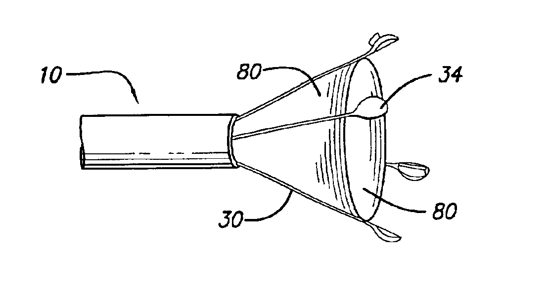
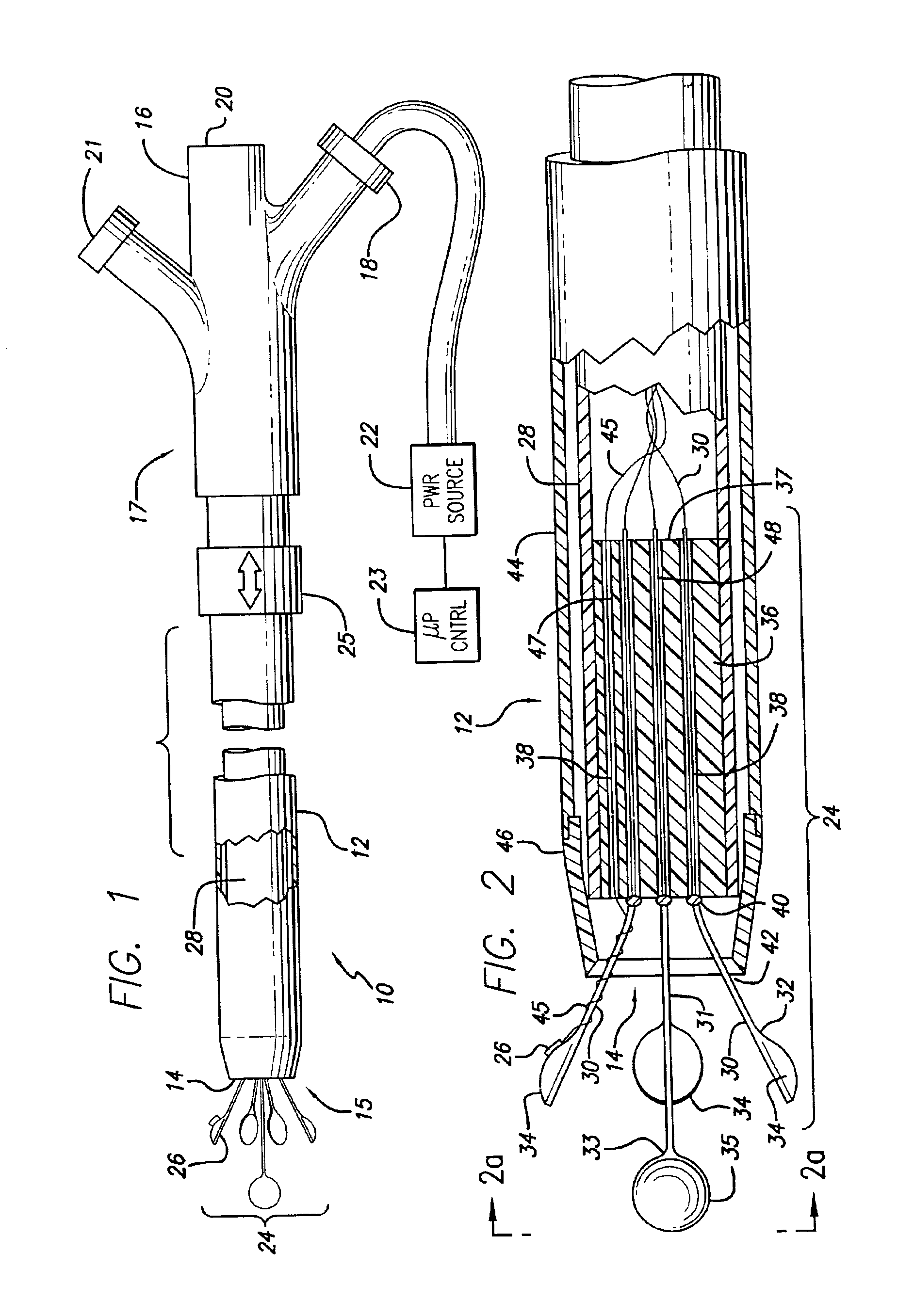
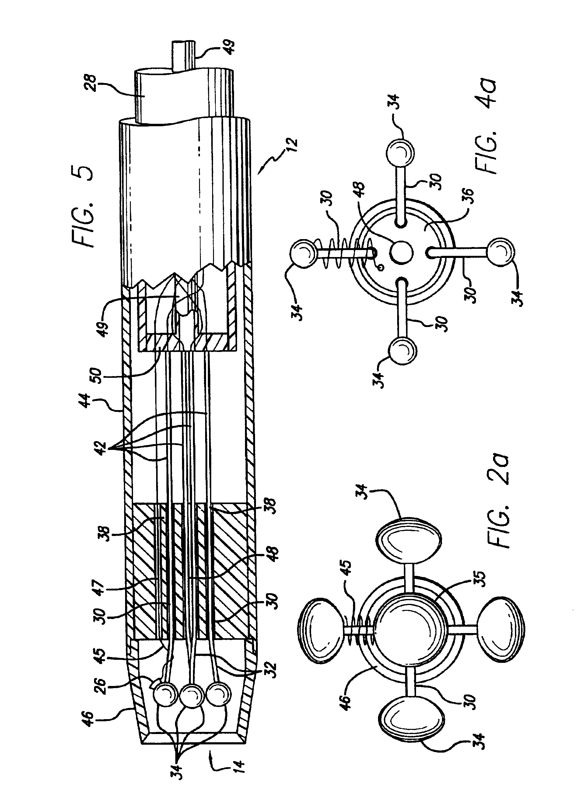
[0053]Turning now to the drawings with more particularity wherein like reference numerals indicate like or corresponding elements among the figures, shown in FIG. 1 is a catheter 10 for applying energy to an anatomical structure such as a vein. The catheter 10 includes an outer sheath 12 having a distal orifice 14 at its working end 15. The connector end 17 of the outer sheath 12 is attached to a handle 16 that includes an electrical connector 18 for interfacing with a power source 22, typically an RF generator, and a microprocessor controller 23. The power source 22 and microprocessor 23 are usually contained in one unit. The controller 23 controls the power source 22 in response to external commands and data from a sensor, such as a thermocouple, located at an intraluminal venous treatment site. In another embodiment, the user can select a constant power output so that automated temperature control is not present and the user can manually adjust the power output in view of the tem...


PUM


Abstract

A catheter includes a plurality of primary leads to deliver energy for ligating a hollow anatomical structure. Each of the primary leads includes an electrode located at the working end of the catheter. Separation is maintained between the primary leads such that each primary lead can individually receive power of selected polarity. The primary leads are constructed to expand outwardly to place the electrodes into apposition with a hollow anatomical structure. High frequency energy can be applied from the leads to create a heating effect in the surrounding tissue of the anatomical structure. The diameter of the hollow anatomical structure is reduced by the heating effect, and the electrodes of the primary leads are moved closer to one another. Where the hollow anatomical structure is a vein, energy is applied until the diameter of the vein is reduced to the point where the vein is occluded. In one embodiment, a balloon is inflated to occlude the structure before the application of energy. Where the structure is a vein, the inflated balloon obstructs blood flow and facilitates the infusion of saline, medication, or a high-impedance fluid to the vein in order to reduce the occurrence of coagulation and to improve the heating of the vein by the catheter. The catheter can include a lumen to accommodate a guide wire or to allow fluid delivery.

Description

[0001]This is a division of co-pending application No. 09 / 497,099 filed on Feb. 3, 2000 Pat. No. 6,398,780, which is a division of Ser. No. 08 / 958,766 filed on Oct. 26, 1997 now U.S. Pat. No. 6,165,172 which is a Continuation-in-part of Ser. No. 08 / 927,251 filed on Sep. 11, 1997 now U.S. Pat. No. 6,200,312, the contents of which are incorporated by reference in their entireties.BACKGROUND OF THE INVENTION[0002]The invention relates generally to a method and apparatus for applying energy to shrink a hollow anatomical structure such as a vein, and more particularly, to a method and apparatus using an electrode device having multiple leads for applying said energy.[0003]The human venous system of the lower limbs consists essentially of the superficial venous system and the deep venous system with perforating veins connecting the two systems. The superficial system includes the long or great saphenous vein and the short saphenous vein. The deep venous system includes the anterior and po...

Claims


Application Information

Patent Timeline
Patent Type & Authority Patents(United States)
IPC IPC(8): A61B18/18A61B17/12A61B17/22A61B18/08A61B18/12A61B18/14
CPCA61B18/1492A61B2218/002A61B2017/22051A61B2017/22067A61B2018/00214A61B2018/0022A61B2018/00404A61B2018/00488A61B2018/00589A61B2018/00898A61B2018/124A61B2018/1253A61B2018/126A61B2019/5278A61B2017/22038A61B2090/3782
Inventor FARLEY, BRIAN E.HENDERSON, DAWN A.JONES, CHRISTOPHER S.PARKER, MARK P.TARTAGLIA, JOSEPH M.
Owner TYCO HEALTHCARE GRP LP
Why Eureka
Try Eureka