
Integral coupling for joining conduit sections

a technology of integrated coupling and conduit section, which is applied in the field of coupling systems for conduit and pipe, can solve the problems of greater than desired cost, complex installation process, etc., and achieve the effect of reducing or eliminating offset, efficient connection, and reducing the amount of time needed to tighten

Inactive Publication Date: 2013-09-12
ATKORE INT
View PDF6 Cites 20 Cited by
  • Summary
  • Abstract
  • Description
  • Claims
  • Application Information

AI Technical Summary

Benefits of technology

The mentioned patent is for a way to connect raised sections of conduit together. It reduces the time needed to tighten the screws or bolts during installation, reduces any damage to the electrical cable, and increases safety by making the connection stronger and more secure.

Problems solved by technology

As can be appreciated, each of the aforementioned schemes suffer from issues relating to greater-than-desired cost, and complexity of installation process.

Method used


Image

  • Integral coupling for joining conduit sections
  • Integral coupling for joining conduit sections
  • Integral coupling for joining conduit sections

Examples


Embodiment Construction

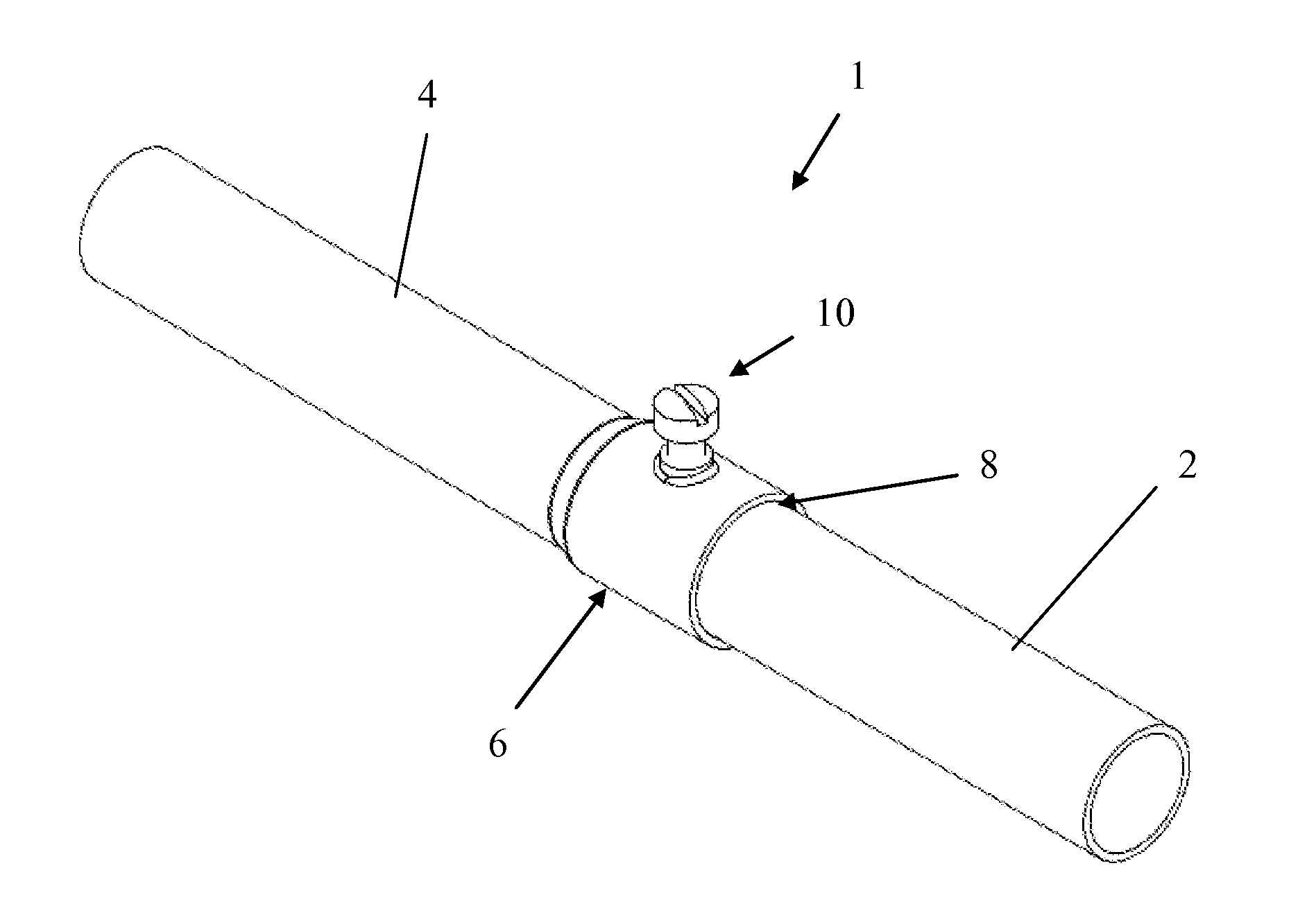
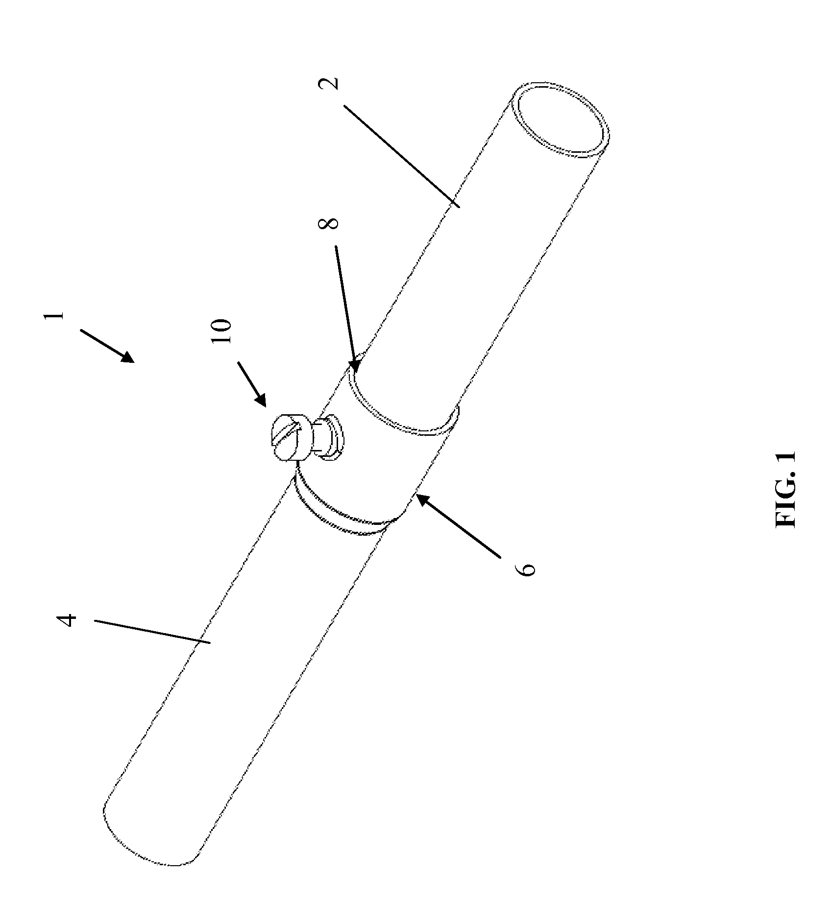
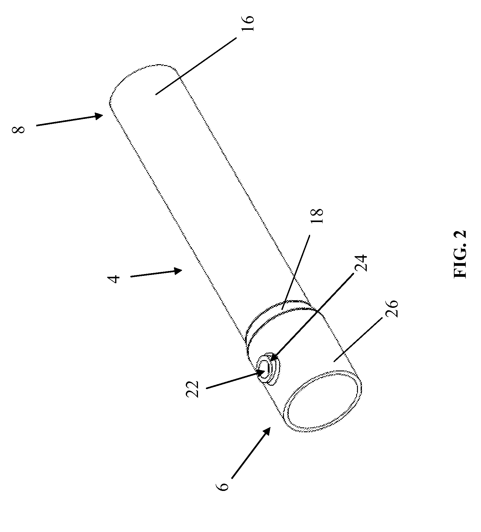
[0022]FIG. 1 shows an exemplary coupling assembly 1 for connecting first and second conduit sections 2, 4 in generally coaxial relationship. The first and second conduit sections 2, 4 can have generally the same outer diameter, and can be of the same or different lengths. At least one of the sections 2, 4 has a bell portion 6 configured to receive an insertion end 8 of the other section. The bell portion 6 has an inner diameter (“ID”FIG. 3A) sized to receive the outer diameter (“OD”FIG. 3A) of the insertion end 8 of the other conduit section.

[0023]To fix the coupling sections 2, 4 together, a fastener 10 is disposed in a wall 12 (FIGS. 3B, 3C) of the bell portion 6 so that a first end 14 (FIGS. 4B, 4C) of the fastener 10 is engageable with an outer surface 16 of the insertion end 8. This arrangement facilitates easy selective locking / unlocking of the first and second conduit sections 2, 4 with respect to each other. As will be appreciated, the disclosed arrangement also provides a d...


PUM

PropertyMeasurementUnit
heightaaaaaaaaaa
lengthaaaaaaaaaa
diameteraaaaaaaaaa

Abstract

A coupling system for conduit and pipe is disclosed. First and second conduit sections are disclosed, each of which has first and second ends. The first end has an outside diameter, and the second end has a belled portion with an inside diameter greater than the outside diameter of the first end. The belled portion has an aperture and a raised lip surrounding the aperture. A threaded fastener is rotatably disposed in the aperture and engages threads of the aperture and an inner surface of the raised lip. The raised lip has a predetermined lip height that is selected to provide a minimum number of full threads engagement between the belled portion and the threaded fastener to ensure the belled portion has a predetermined pull out strength. Other embodiments are disclosed and claimed.

Description

BACKGROUND OF THE INVENTION[0001]1. Field of the Invention[0002]Embodiments of the invention generally relate to the field of coupling systems for conduit and pipe used to contain electrical cable or wiring, and more particularly to an improved conduit coupling assembly for connecting multiple lengths of electrical conduit in coaxial relationship.[0003]2. Discussion of Related Art[0004]It is a conventional practice in many types of pipe or conduit systems, and particularly in electrical systems employing tubular conduits that contain electrical wires or cables, to connect a number of lengths of conduit in end-to-end relation through means of couplings so as to form a continuous conduit system as desired for a particular application. In the case of thin wall conduit, which is primarily employed for encasing electrical cable or conductor wires in applications where the conduit will not be subjected to large stresses, compression fittings or coupling assemblies may be employed which ar...

Claims


Application Information

Patent Timeline
Patent Type & Authority Applications(United States)
IPC IPC(8): F16L9/22B23P19/00
CPCY10T29/49826F16L25/065
Inventor HENTHORN, KEVINSCARTOZZI, GIULIOFLOREK, JAMES E.
Owner ATKORE INT
Learn More