Antenna apparatus
a technology of antenna and antenna body, which is applied in the direction of antennas, antenna details, protective materials radiating elements, etc., can solve the problem of not disclosing the physical properties of the molded body adjustment, and achieve the effect of miniaturizing the size and improving the antenna characteristics
- Summary
- Abstract
- Description
- Claims
- Application Information
AI Technical Summary
Benefits of technology
Problems solved by technology
Method used
Image

Examples
first embodiment
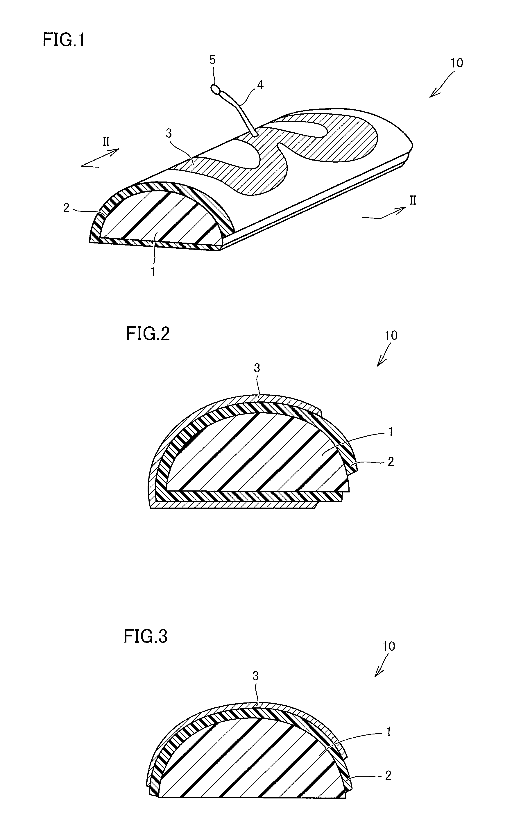
[0051]A first embodiment of an antenna apparatus according to the present invention will be described with reference to FIGS. 1 and 2. As shown in FIGS. 1 and 2, an antenna apparatus 10 according to the present invention includes a base 1 made of a dielectric, and a flexible substrate 2 fixed on a surface of base 1. On the surface of flexible substrate 2, an antenna conductor 3 is formed to have a predetermined planar shape. A leading wire 4 is connected to antenna conductor 3. Leading wire 4 has the one end connected to antenna conductor 3 and the other opposite end connected to a terminal 5.
[0052]A cross-sectional shape of base 1 is semicircular as shown in FIG. 2. In other words, while a bottom face of base 1 is substantially planar, and an upper face of base 1 is curved. Flexible substrate 2 is fixed to base 1 so as to extend from the curved face (the curved face bulging outward) to the back face of base 1.
[0053]Flexible substrate 2 can be fixed to base 1 by any given method. Fo...
second embodiment
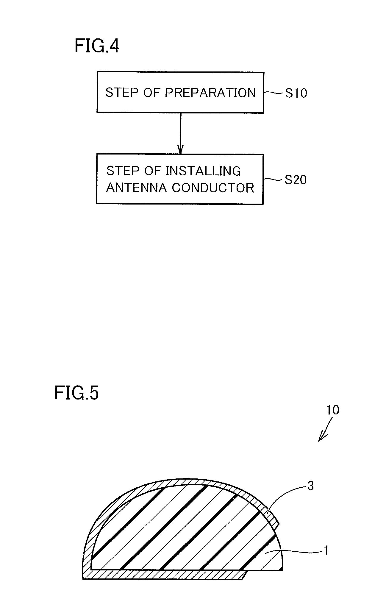
[0061]A second embodiment of the antenna apparatus according to the present invention will be described with reference to FIG. 5.
[0062]Antenna apparatus 10 shown in FIG. 5 basically has a structure similar to that of antenna apparatus 10 shown in FIGS. 1 and 2, but is different in that antenna conductor 3 is formed directly on the surface of base 1. In other words, antenna apparatus 10 shown in FIG. 5 has antenna conductor 3 formed directly on the surface of base 1 without employing flexible substrate 2 (refer to FIGS. 1 and 2). Leading wire 4 (refer to FIG. 1) is connected to antenna conductor 3 in a manner similarly employed in the antenna apparatus shown in FIG. 1, and terminal 5 (refer to FIG. 1) is provided on the other end of leading wire 4.
[0063]As a method for manufacturing antenna conductor 3, the method of applying a metal paste on the surface of base 1 so as to take the shape of antenna conductor 3 and applying a hardening treatment may be employed. Alternatively, any oth...
third embodiment
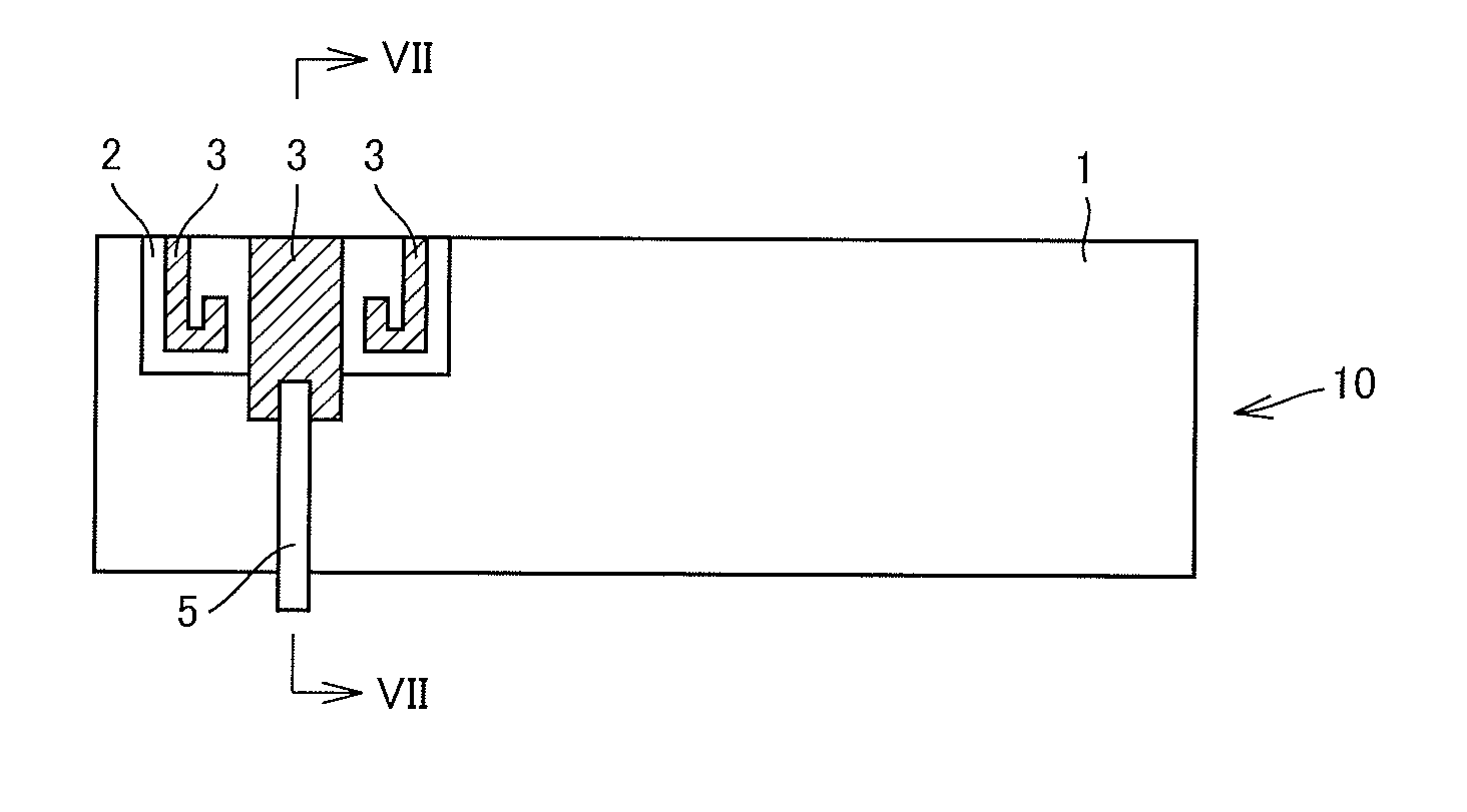
[0065]A third embodiment of the antenna apparatus according to the present invention will be described with reference to FIGS. 6 and 7.
[0066]Antenna apparatus 10 shown in FIGS. 6 and 7 basically has a structure similar to that of antenna apparatus 10 shown in FIGS. 1 and 2, but is different from antenna apparatus 10 shown in FIGS. 1 and 2 in the shapes of base 1 and flexible substrate 2. In other words, base 1 constituting antenna apparatus 10 shown in FIGS. 6 and 7 has a curved outer peripheral surface and is hollow inside. Describing in a different point of view, base 1 has a shape such that a plate body having a substantially constant thickness is bent. Further, flexible substrate 2 is arranged on a part of the surface of base 1. Antenna conductor 3 is arranged on the surface of flexible substrate 2. A part of the end of flexible substrate 2 is bent so as to extend away from the surface of base 1, as shown in FIG. 7. Terminal 5 is connected to antenna conductor 3 at the bent port...
PUM
 Abstract
Description
Claims
Application Information
 - R&D
- Intellectual Property
- Life Sciences
- Materials
- Tech Scout
- Unparalleled Data Quality
- Higher Quality Content
- 60% Fewer Hallucinations
Browse by: Latest US Patents, China's latest patents, Technical Efficacy Thesaurus, Application Domain, Technology Topic, Popular Technical Reports.
© 2025 PatSnap. All rights reserved.Legal|Privacy policy|Modern Slavery Act Transparency Statement|Sitemap|About US| Contact US: help@patsnap.com