Tube luminescent retrofit using light emitting diodes

a technology of light-emitting diodes and tubes, which is applied in the field of illumination systems, can solve the problems of loss of light emitted by each led, difficult fabrication of curved reflection surfaces, etc., and achieve the effect of reducing the cost and the complexity of lamps

Active Publication Date: 2013-09-12
KONINKLIJKE PHILIPS ELECTRONICS NV
View PDF2 Cites 20 Cited by
  • Summary
  • Abstract
  • Description
  • Claims
  • Application Information

AI Technical Summary

Benefits of technology

[0025]In an embodiment, the unit may further include a diffusing cover configured to diffusively transmit light incident thereon, where the first diffusing portion may be configured to diffusively reflect the light incident thereon to be incident on the diffusing cover. This embodiment provides for additional diffusion by a diffusively transmitting cover. In a preferred embodiment, each beam of the first portion of light emitted by the LED is diffusively reflected only once by the first diffusing portion before either being directly transmitted out of the unit or being diffusively transmitted out of the unit via the cover. The light being reflected in this manner allows keeping light losses to a minimum.
[0026]In an embodiment, the LED may co

Problems solved by technology

One drawback of such an arrangement is that providing a curved reflection surface poses fabrication challenges.
Another drawback is that some of the light emi

Method used


Image

  • Tube luminescent retrofit using light emitting diodes
  • Tube luminescent retrofit using light emitting diodes
  • Tube luminescent retrofit using light emitting diodes

Examples


Embodiment Construction

[0059]In the following description, numerous specific details are set forth to provide a more thorough understanding of the present invention. However, it will be apparent to one of skill in the art that the present invention may be practiced without one or more of these specific details. In other instances, well-known features have not been described in order to avoid obscuring the present invention.

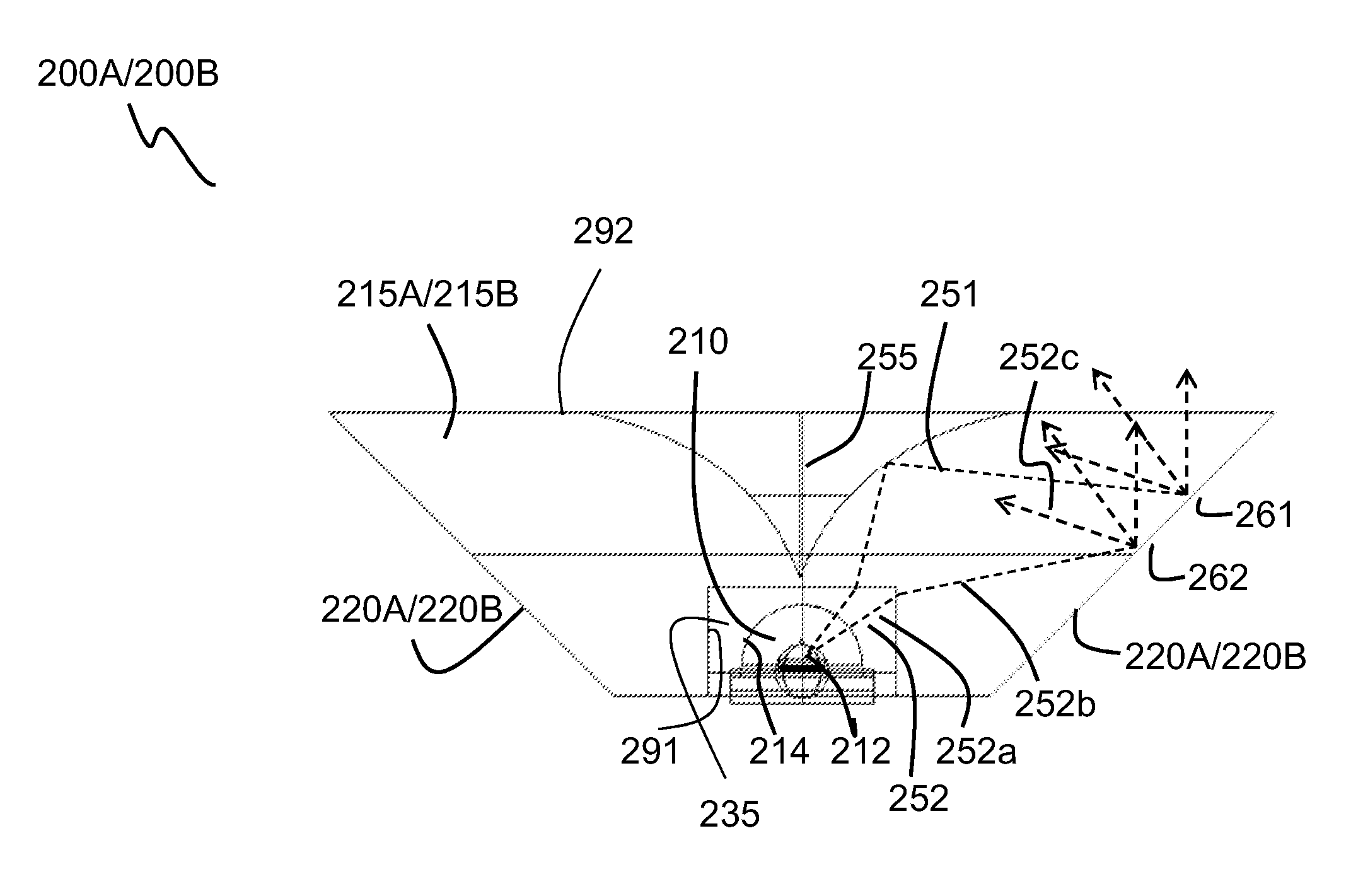
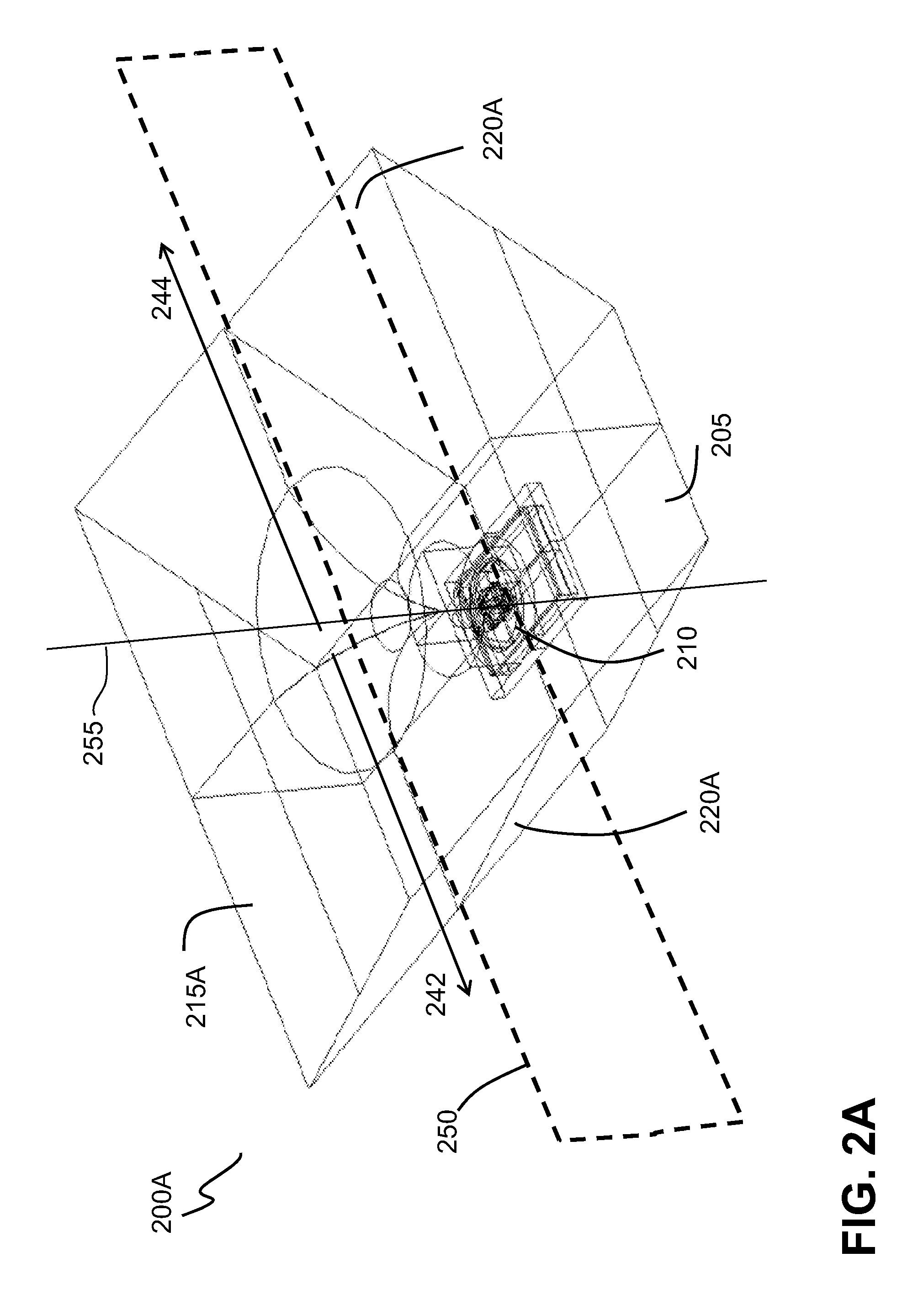
[0060]FIG. 2A illustrates a three-dimensional view of an optical unit 200A, according to one embodiment of the present invention. As shown, the unit 200A includes a LED 210 encompassed by a module 215A and disposed on the same plane (e.g., the top surface of a printed circuit board) as a bottom surface 205 of the module 215A. Side surfaces 220A of the module 215A are made so that they diffusively reflect light incident on them. The bulk of the module 215A is a re-directing and light propagating structure configured to guide the light emitted by the LED 210 to be incident onto the side s...


PUM


Abstract

The invention relates to a LED-based optical unit including a LED disposed on a surface and a monolithic module encompassing the LED and including a re-directing portion and a first diffusing portion. The first diffusing portion is configured to diffuse light incident thereon. The re-directing portion is configured to re-direct at least a first portion of light emitted by the LED to be incident on the first diffusing portion.

Description

FIELD OF THE INVENTION[0001]Embodiments of the present invention relate generally to the field of illumination systems, and, more specifically, to LED-based optical units.DESCRIPTION OF THE RELATED ART[0002]As the efficacy (measured in lumen per Watt) and the luminous flux (measured in lumen) of light emitting diodes (LEDs) increases and prices go down, it is expected that LED illumination and LED based lamps soon will be serious alternatives to and at a competitive level with until now predominant tube luminescent (TL) based lamps for providing large-area illumination. Such lamps are typically found in office buildings in forms of 15 centimeter- to 2.4 meter-long tubes, having diameters ⅝ inch, 1 inch, 1.25 inch or even larger, providing uniform luminance along the length of the tube. A typical TL luminous flux output density is 3000 lumen per meter tube length. For LED retrofit, also lower values may be found.[0003]Current LED lamps are fabricated by placing a large number of LEDs...

Claims


Application Information

Patent Timeline
IPC IPC(8): F21V7/00
CPCG02B6/0073F21S8/04F21V5/04F21V7/0066F21Y2101/02F21Y2103/003F21W2131/402F21Y2103/10F21Y2115/10
Inventor VAN DER SIJDE, ARJEN GERBENHEEMSTRA, TEWE HIEPKE HIEPKEPFEFFER, NICOLA BETTINA BETTINA
Owner KONINKLIJKE PHILIPS ELECTRONICS NV
Why Eureka
Try Eureka