Rotary hay wedge for round balers

a hay wedge and round baler technology, applied in baling, presses, packaging, etc., to achieve the effect of better results

Inactive Publication Date: 2013-09-19
FORAGE INNOVATIONS
View PDF5 Cites 3 Cited by
  • Summary
  • Abstract
  • Description
  • Claims
  • Application Information

AI Technical Summary

Benefits of technology

[0013]Hence it is a first object of the present invention to provide a baler for producing round agricultural bales of crop material that yields better results. In particular it is an object of the present invention to provide a baler that solves the above-mentioned drawbacks of the prior art balers. A further object of the invention is to at least provide an alternative for the known balers.
[0014]Accordingly there is a need for an improvement that will reduce the amount of these extra strands of hay that are generated while a bale is being formed so that the completed bales do not have these extra strands of hay on the edges. Such an improvement reduces operational problems associated with build-up of loose strands of hay, and has also been found to improve the appearance of the finished bale. Further, when net wrap is being applied, it is desired to cause the outside edges of the bale to have a shape that allows the net wrap to go over the edges more easily. This additionally provides an improved aesthetic appearance to the bale.
[0017]When the bale is completed and net wrap is being applied, the outside edges of the bale will have a shape that allows the net wrap to go over the edges more easily. The rotary hay wedge is also pushing against the net on the edges trying to tuck it around the corners better. This gives an improved aesthetic appearance.
[0018]This type of device could be used on any round baler both current production and even possibly retro-fittable. The advantage that this provides is that it would eliminate potential down time from the problems that are caused by hay buildup.

Problems solved by technology

It pushes into the bale throughout formation, either tucking the edges in or knocking the strands of hay off before the hay can get to an area that it causes problems.

Method used


Image

  • Rotary hay wedge for round balers
  • Rotary hay wedge for round balers
  • Rotary hay wedge for round balers

Examples


Embodiment Construction

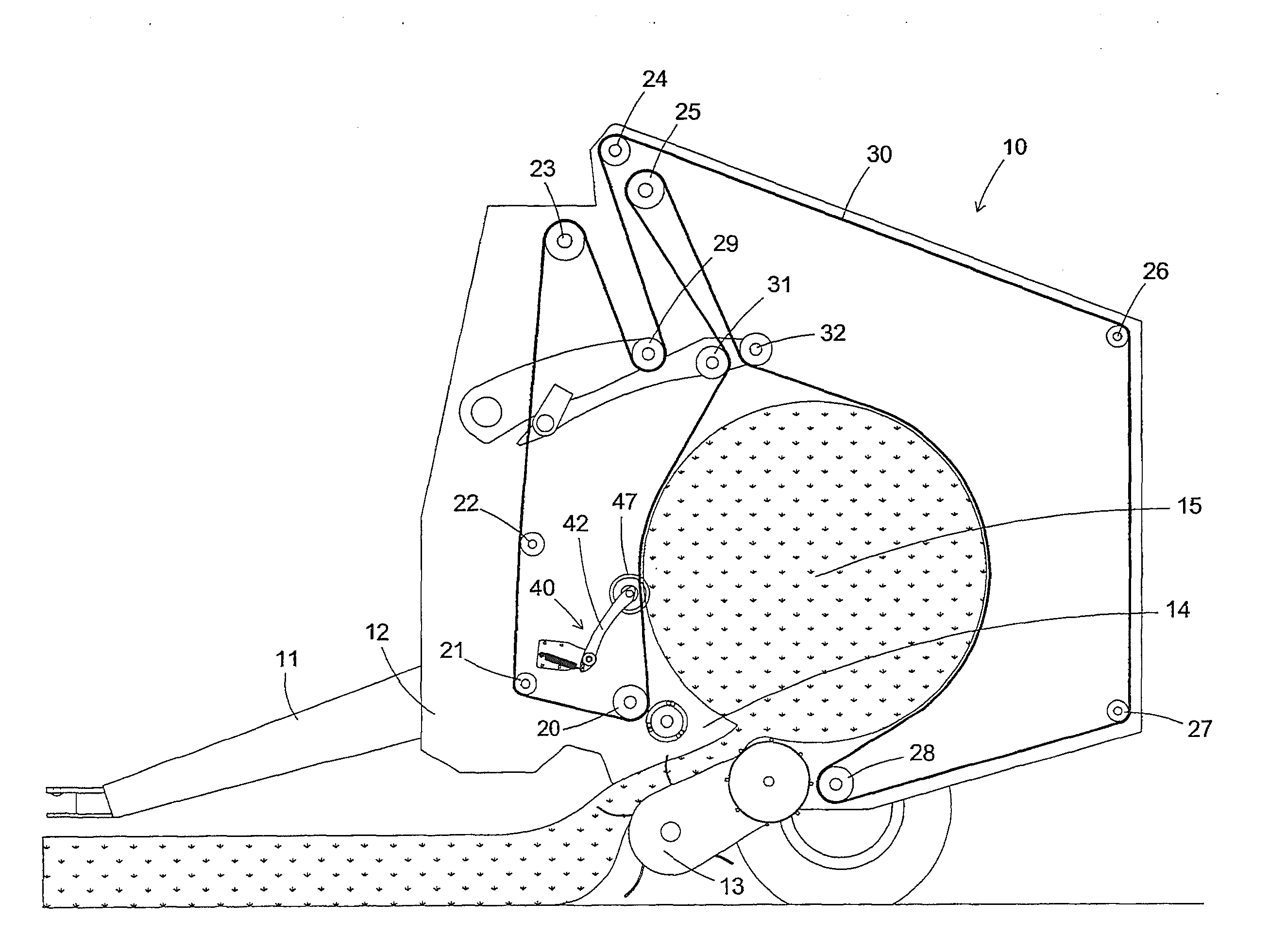
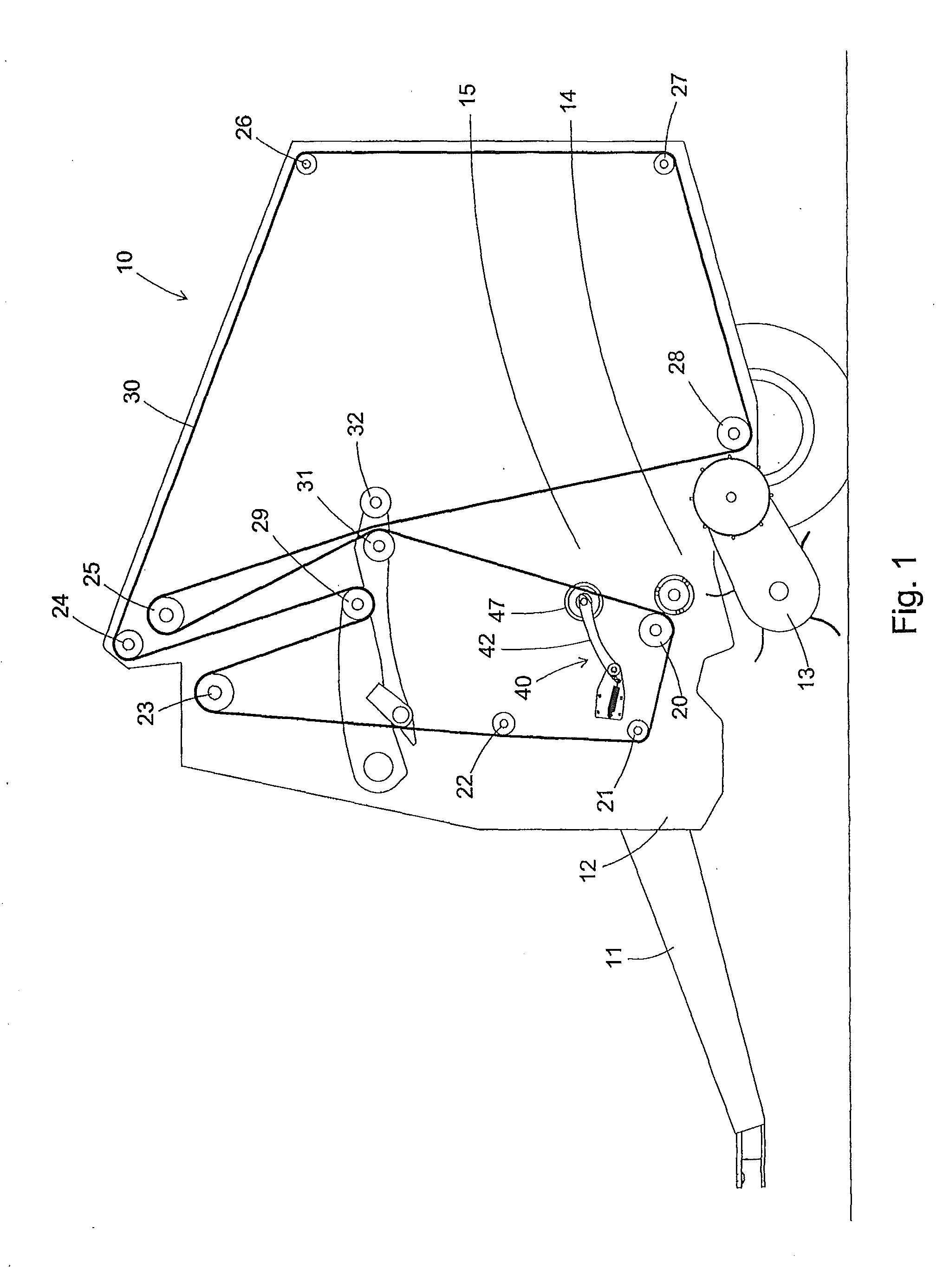
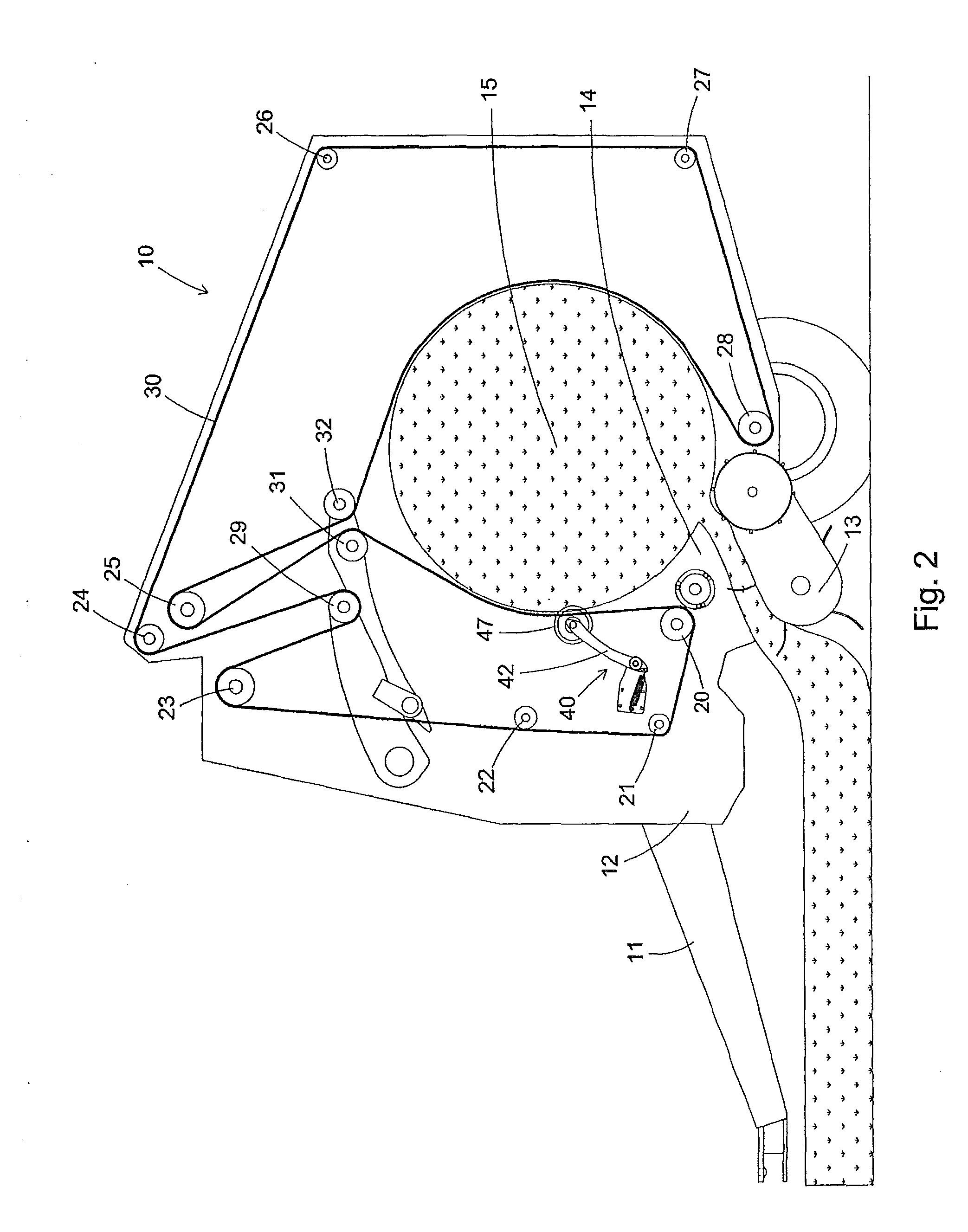
[0038]The following is a description of certain embodiments of the invention, given by way of example only and with reference to the drawings. FIG. 1 shows a baler 10 having a tongue 11 attached to a frame 12. A pickup 13 picks up hay or other material to be baled from the ground and delivers it to an inlet 14 of a baling chamber 15 of the baler 10. A plurality of rotatable members / rollers 20, 21, 22, 23, 24, 25, 26, 27, 28 are operatively rotatably attached to the frame 12 about fixed parallel substantially horizontal axes. Belts 30 are trained around the fixed rollers 20-28 and around moveable rollers 29, 31 and 32 which are disposed about moveable parallel axes which are also parallel to the axes of the fixed axis rollers 20-28. The operation of this baler is explained in detail in U.S. Pat. No. 7,395,756, which is hereby incorporated by reference in its entirety. It is to be understood, however, that the present invention is not limited to a belt type round baler but could be us...


PUM


Abstract

A baler with a pickup and a baling chamber with an inlet, the bale forming chamber having a first and second side panel, a plurality rollers rotatably disposed respectively about parallel axes. A bale edge engaging member is rotatably attached to the frame about an axis of rotation substantially parallel to said axes of the rollers, the bale edge engaging member being disposed adjacent an inside portion of one of the side panels in overlapping arrangement with a bale being formed in the baling chamber at least at times when a bale is being formed. The bale edge engaging member is spaced from the inlet to the bale forming chamber so as to not impede material entering the bale forming chamber from a pickup. Alternate embodiments have the rotatable bale edge engaging member / disc on a fixed axis adjacent the baling chamber when the bale is almost completed.

Description

CROSS REFERENCE TO RELATED APPLICATIONS[0001]This application is a continuation of PCT application number PCT / NL2011 / 000069 filed on 26 Oct. 2011, which claims priority from U.S. provisional application No. 61 / 407,648 filed on 29 October 2010. Both applications are hereby incorporated by reference in their entireties.BACKGROUND OF THE INVENTION[0002]1. Field of the Invention[0003]The present invention relates to a baler, in particular an agricultural baler for producing so-called round bales of crop material.[0004]2. Description of the Related Art[0005]Such a baler is known from for example U.S. Pat. No. 7,395,756, which shows a basic round baler of the type used in this art.[0006]As a round bale is being created in a baler, some of the hay usually comes out between the belts and the sides of the baler. This is a problem because the extra strands of hay need to be removed before the hay can get to an area that it causes problems, or because the presence of these loose strands of hay...

Claims


Application Information

Patent Timeline
Patent Type & Authority Applications(United States)
IPC IPC(8): A01F15/07A01F15/08
CPCA01F15/0715A01F15/085A01F15/071A01F15/0833
Inventor JAHRAUS, DAVID WAYNEBANDSTRA, JERRY EUGENEWILLIAMS, JAMES S.VAN ROEKEL, HENRY W.
Owner FORAGE INNOVATIONS
Why Eureka
Try Eureka