Baling device to form bales of crop material

a baling device and crop material technology, applied in baling, presses, loaders, etc., can solve the problems of inability to use the baling device, inability to deliver crop material at different locations, and inability to open and close the rear flap, so as to achieve a positive influence on the overall dimensions of the baling devi

Inactive Publication Date: 2013-09-19
LELY PATENT
View PDF2 Cites 0 Cited by
  • Summary
  • Abstract
  • Description
  • Claims
  • Application Information

AI Technical Summary

Benefits of technology

[0025]By arranging the outlet of the intake device at a fixed position on a frame, and by providing three movable guiding elements which are alternately located at opposite sides of the outlet to receive crop material between the respective guiding elements provides a simple and efficient system for the formation of bales of crop material.
[0028]In an embodiment, the bale forming device comprises at least four movable guiding elements. The provision of four movable guiding elements has the advantage that an alternating one of the at least four movable guiding elements may be used to form a back end support of the endless belt. As a result no separate fixed support element has to be provided which has to be positioned relative high at the back side of the baling device to make passing of the movable guiding elements between the baling chamber and the fixed support element possible. Thus, the use of a movable guiding element as back end support of the endless belt has a positive influence on the overall dimensions of the baling device.
[0030]In one embodiment five or six movable guiding elements are provided. The advantage of five or six movable guiding elements is that alternately two movable guiding elements may be used for formation of a bale, two movable guiding elements may be ready to be used for the formation of bale after formation of a previous bale is finished, and one or two further movable guiding elements may be used to form back end support for the endless belt so that the endless belt at the back end of the baling device does not interfere with the endless belt part surrounding the bale to be formed. By reservation of two movable guiding elements, i.e. positioned close by the outlet of the intake device, for the formation of a new bale, minimum time is required to restart baling after formation of a previous bale has finished.
[0034]As an alternative or in addition thereto, the baling device may comprise a guiding rail to guide the movable guiding elements at least along the outlet of the intake device. At the outlet of the intake device, the movable guiding elements run close to other parts of the baling device, in particular close to rollers of the intake device forming the outlet of the intake device. To avoid any collision between the movable guiding rollers and the rollers of the intake device, a guiding rail may be provided to control the movement of the movable guiding rollers more accurately.

Problems solved by technology

The opening and closing of the rear flap takes considerable time, during which the baling device cannot be used for formation of a new bale.
A drawback of the device of EP 1 264 532 is that the intake device must be configured to deliver crop material at different locations.
The provision of such intake device configured to deliver crop material at different locations makes the baling device relative complex.
Another drawback of the baling device of EP 1 264 532 is that the baling device is relative long due to the presence of two bale forming chambers.

Method used


Image

  • Baling device to form bales of crop material
  • Baling device to form bales of crop material
  • Baling device to form bales of crop material

Examples


Embodiment Construction

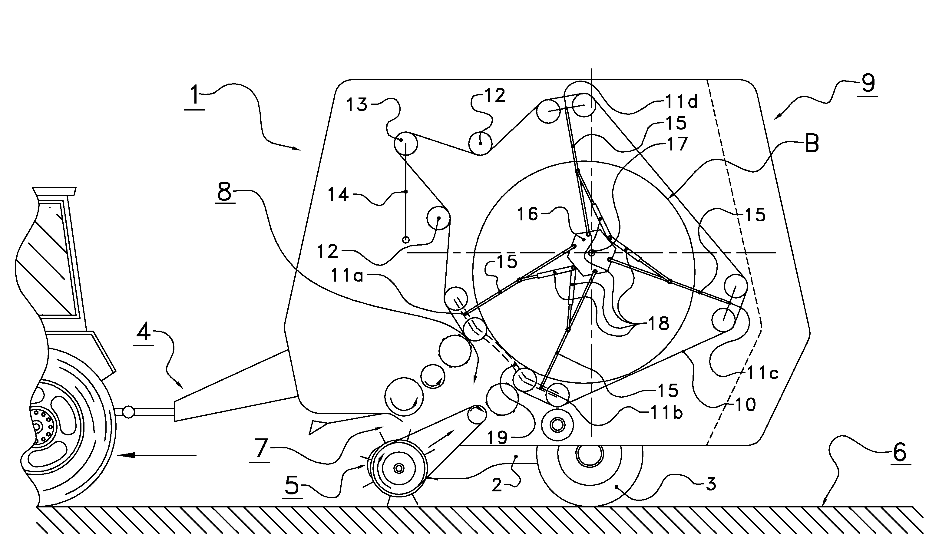
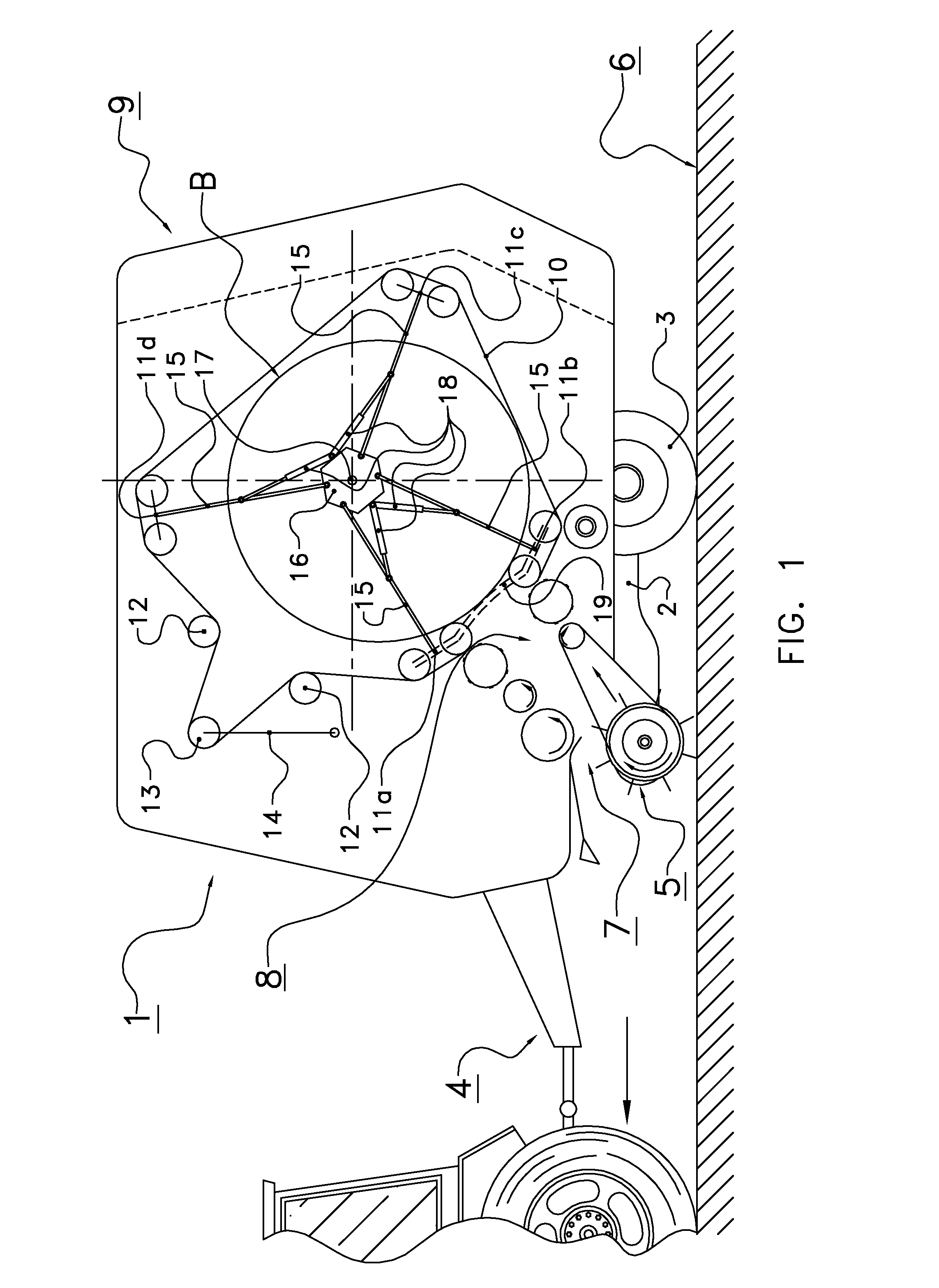
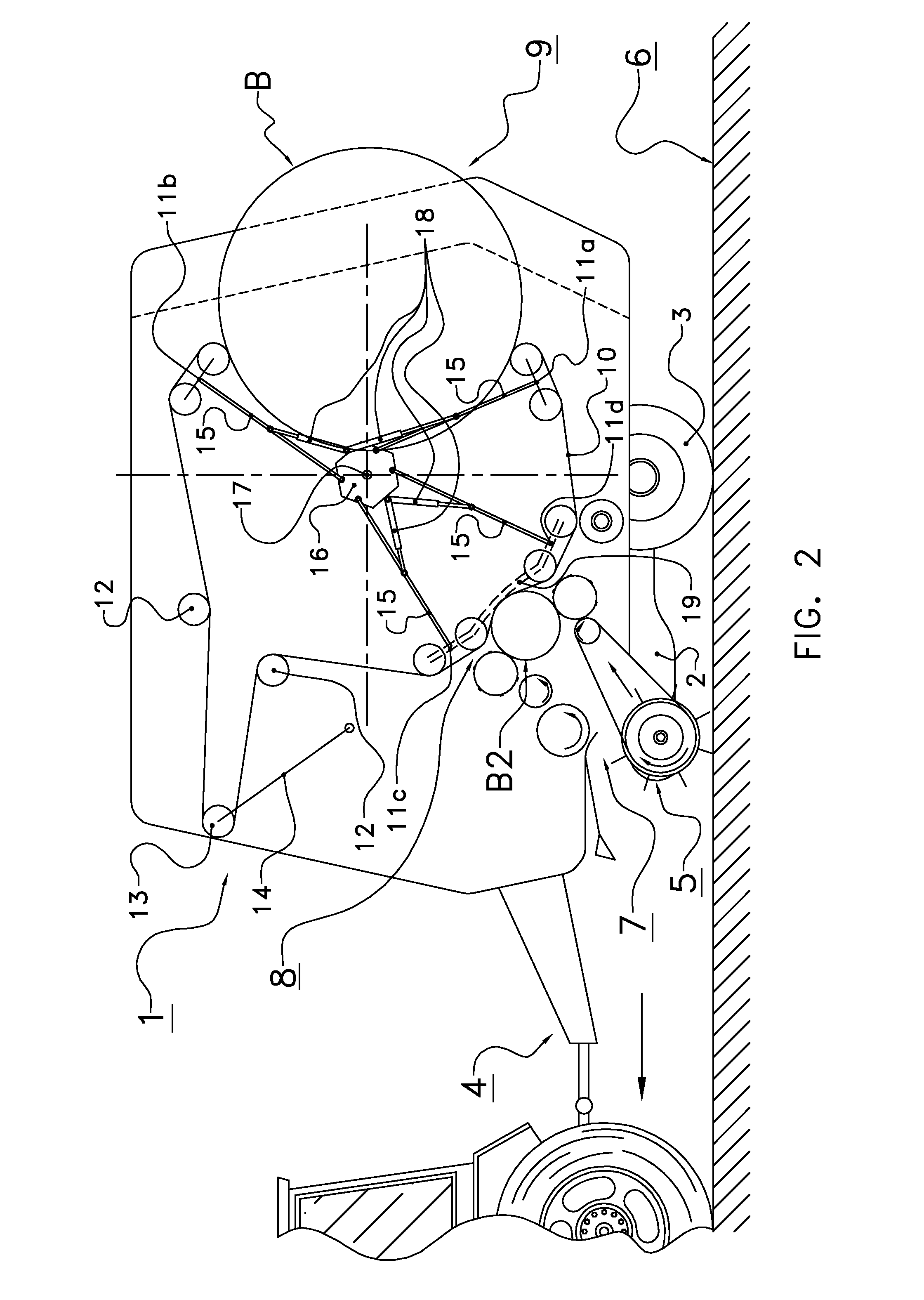
[0047]The following is a description of certain embodiments of the invention, given by way of example only and with reference to the drawings. Referring to FIG. 1, it shows a baling device, generally indicated with the reference numeral 1. The baling device 1 comprises a frame 2 which is supported by wheels 3. The baling device 1 is configured to be connected at its front end 4 to a pulling vehicle, for instance a tractor.

[0048]The baling device 1 comprises an intake device 5 to take in crop material, such as silage, grass, hay, from a ground surface 6. The intake device 5 comprises an inlet 7 and an outlet 8.

[0049]Via the inlet 7 crop material is taken from the ground and transported to the outlet 8. A roll provided at the inlet 7 may be provided with tines to facilitate the picking up of crop material.

[0050]A bale forming device 9 is arranged on the frame 2 to form bales of crop material. The bale forming device 9 comprises an endless belt 10 and a number of movable guiding elemen...


PUM


Abstract

The invention relates to a baling device to form bales of crop material, including a frame, an intake device, a bale forming device for forming a bale of the crop material, the bale forming device including at least one endless belt to delimit a baling chamber, and a number of guiding elements to guide the endless belt, wherein the outlet of the intake device is located at a fixed position with respect to the frame, and that at least three guiding elements are movably mounted with respect to the outlet of the intake device to position for subsequent bales different pairs of two guiding elements of the at least three movable guiding elements at the opposite sides of the outlet.

Description

CROSS REFERENCE TO RELATED APPLICATIONS[0001]This application is a continuation of U.S. patent application Ser. No. 13 / 456,228 filed 26 Apr. 2012, which is a continuation of PCT application number PCT / NL2010 / 000146 filed on 19 Oct. 2010, which claims priority from Netherlands application number 1037433 filed on 2 Nov. 2009. All applications are hereby incorporated by reference in their entireties.BACKGROUND OF THE INVENTION[0002]1. Field of the Invention[0003]The present invention relates to a baling device to form bales of crop material.[0004]A baling device is an agricultural unit to form bales of crop material. The baling device usually comprises an intake device to take up crop material from a ground surface and a bale forming device to form a bale from the crop material.[0005]2. Description of the Related Art[0006]In a known embodiment, the bale forming device comprises an endless belt guided by guiding rollers. An outlet of the intake device is arranged between two guiding rol...

Claims


Application Information

Patent Timeline
Patent Type & Authority Applications(United States)
IPC IPC(8): A01F15/07
CPCA01F15/0705A01D89/001A01F15/0883A01F15/18A01F2015/077
Inventor REIJERSEN VAN BUUREN, WILLEM JACOBUS
Owner LELY PATENT
Why Eureka
Try Eureka