
Offshore Wind Turbine with Device for Ice Prevention

a wind turbine and ice prevention technology, applied in the direction of machines/engines, liquid fuel engines, sustainable manufacturing/processing, etc., can solve the problems of affecting the operation, and affecting the efficiency of wind turbines, so as to increase the salt concentration and increase the concentration

Active Publication Date: 2008-12-25
LM GLASSFIBER
View PDF4 Cites 16 Cited by
  • Summary
  • Abstract
  • Description
  • Claims
  • Application Information

AI Technical Summary

Benefits of technology

[0010]The object of the invention is to show a simple and efficient system to prevent icing on the blades of an offshore wind turbine.
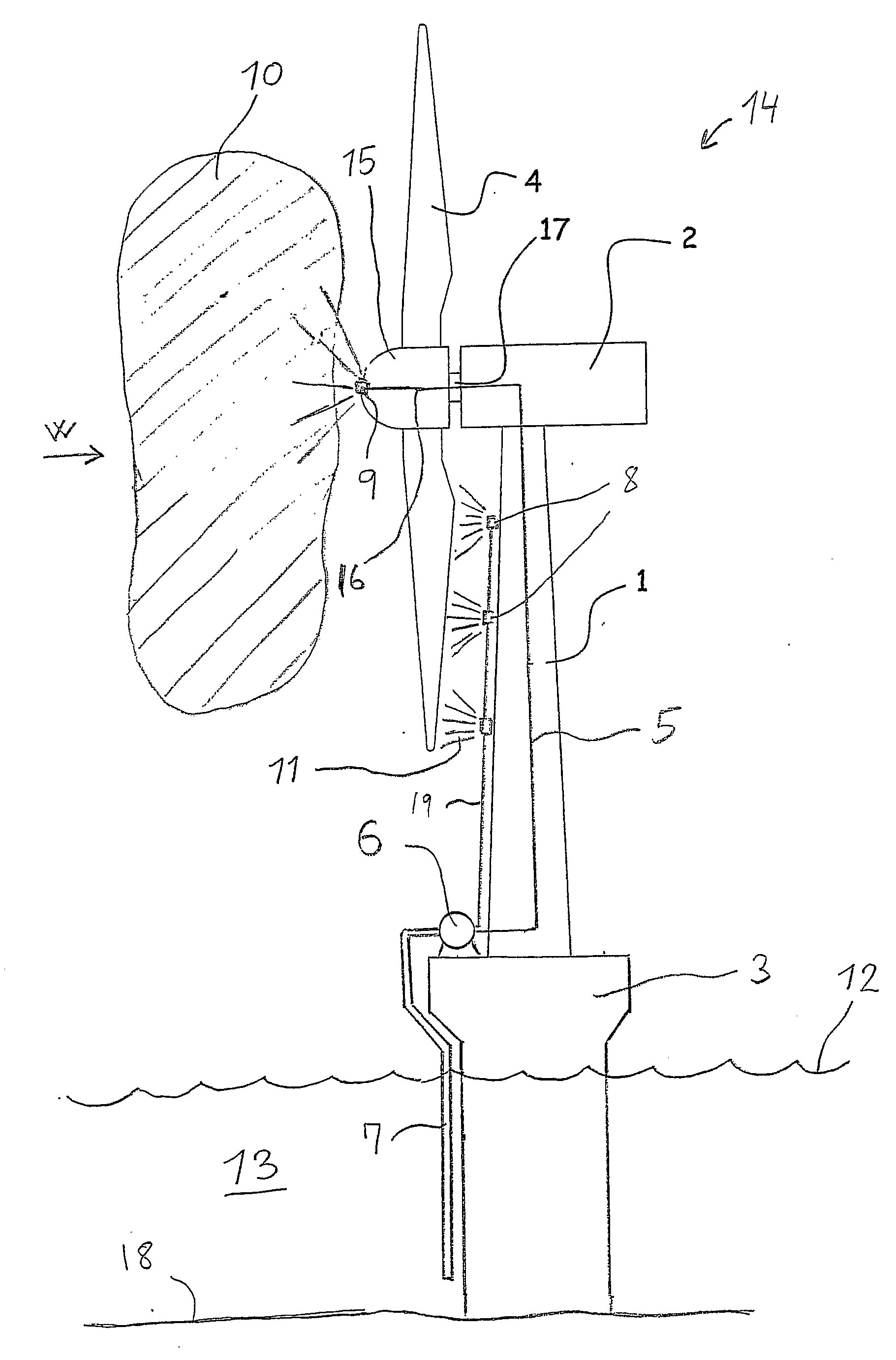
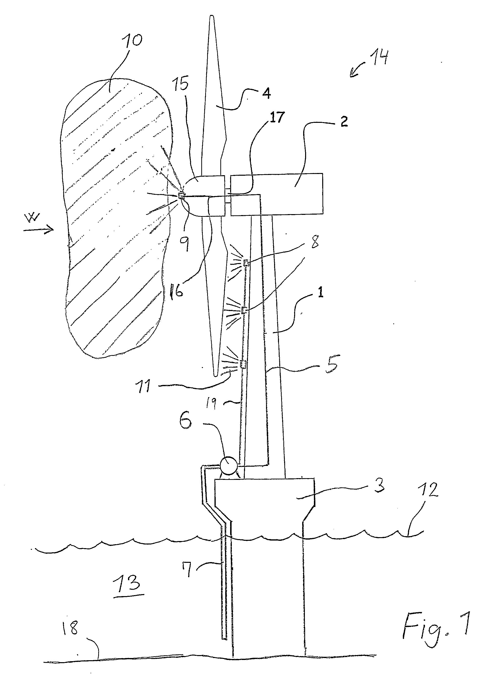
[0014]The nozzles can for instance be placed on a length corresponding to the length of the blade of the wind turbine. The nozzles can emit sea water during the rotation of the rotor, hereby all blades, typically there are three of them, are supplied with sea water while rotating. The wind turbine can also include a system which ensures that each individual blade can be brought to a temporary halt across from the tower for a short time.
[0025]At the suction side the pump can be connected to a suction hose extending down below sea level. The suction hose can have an opening close the bottom of the sea. As salt water is the heavier, the higher the salt concentration, the salt concentration is typically highest at the bottom of the sea. By sucking up salt water with the highest salt concentration possible, efficient ice control can be achieved.
[0026]The pump can also be placed below sea level, possibly inside the tower. This can be advantageous, as pumping up water to high levels is easier than sucking it up.
[0028]According to a particular embodiment the wind turbine can include an appliance, which increases the salt concentration in the salt water which is directed out onto the surface of the blades. The sea water can for instance be directed through an appliance, in which the water evaporates, causing an increased concentration. It is also possible to increase the salt concentration by means of so-called reverse osmosis. Alternatively additional salt can be added to the water.

Problems solved by technology

Icing of wind turbine blades is a widespread problem with several negative results.
Icing can change the profile of the blade and thus the aerodynamic properties of the blade, impeding efficiency.
Furthermore, non-uniform icing can cause severe asymmetric stress to the wind turbine structure, which can result in the operation having to be interrupted.

Method used


Image

  • Offshore Wind Turbine with Device for Ice Prevention
  • Offshore Wind Turbine with Device for Ice Prevention

Examples


Embodiment Construction

[0031]The offshore wind turbine diagrammatically shown in FIG. 1 includes a base 3 standing at the bottom 18 of the sea 13. The base 3 which forms a part of the tower 1 of the wind turbine rises above sea level 12. The tower 1 of the wind turbine extends further up from the base and supports a nacelle 2, also called a cap of the wind turbine. A substantially horizontal main shaft 17 extends from the nacelle 2, a rotor including a hub 15 and a plurality of blades 4 being mounted on said main shaft. The nacelle 2 can yaw, which means it can pivot around a vertical shaft in relation to the tower 1, hereby being able to adjust the rotor in relation to the direction of the wind. The wind turbine shown is a so-called upwind rotor, where the wind hits the rotor before the tower 1. A pump 6 is placed on the base 3. At the suction side said pump communicates with a suction hose 7 extending down below sea level 12, thus being able to pump up sea water. At the delivery side the pump 6 communic...


PUM


Abstract

Offshore wind turbine (14) including a tower (1) rising above sea level (12) and one or ore blades (4), which can be put into rotation by wind. The offshore wind turbine includes a pump (6), which is adapted to pump sea water (13) up form the sea. At the delivery side the pump (6) communicates with nozzles (8, 9), said nozzles being adapted to direct sea water to the surface of the blades (4).

Description

TECHNICAL FIELD[0001]The invention relates to an offshore wind turbine including a tower rising above sea level and one or more blades, which can be put into rotation by wind, and where the offshore wind turbine includes a pump, which is adapted to pump sea water up from the sea.BACKGROUND ART[0002]Modern wind turbines, also called wind motors or wind engines, are employed to produce electricity, They are often very large structures with blades measuring up to 60 meters or more, and which are made from fibre-reinforced polymer shells.[0003]Icing of wind turbine blades is a widespread problem with several negative results. Icing can change the profile of the blade and thus the aerodynamic properties of the blade, impeding efficiency. Furthermore, non-uniform icing can cause severe asymmetric stress to the wind turbine structure, which can result in the operation having to be interrupted.[0004]DE 196 21 485 discloses a wind turbine blade, the inside of which is heated by means of warm...

Claims


Application Information

Patent Timeline
IPC IPC(8): F03B15/06
CPCE02B2017/0091F03D1/00F05B2240/123F05B2240/95F05B2260/601Y02E10/721F03D80/50Y02P80/158F03D13/25Y02E10/727F03D9/28F03D80/40Y02E10/725Y02E10/72Y02P80/10F03D9/00
Inventor GRABAU, PETER
Owner LM GLASSFIBER
Learn More