Microfluidic device for cell motility screening and chemotaxis testing
a microfluidic device and cell technology, applied in the field of microfluidic devices, can solve the problems of affecting the function of the cell, and the shear force caused by the fluid manipulation is difficult to avoid
- Summary
- Abstract
- Description
- Claims
- Application Information
AI Technical Summary
Benefits of technology
Problems solved by technology
Method used
Image
Examples
example 1
Microfluidic Device
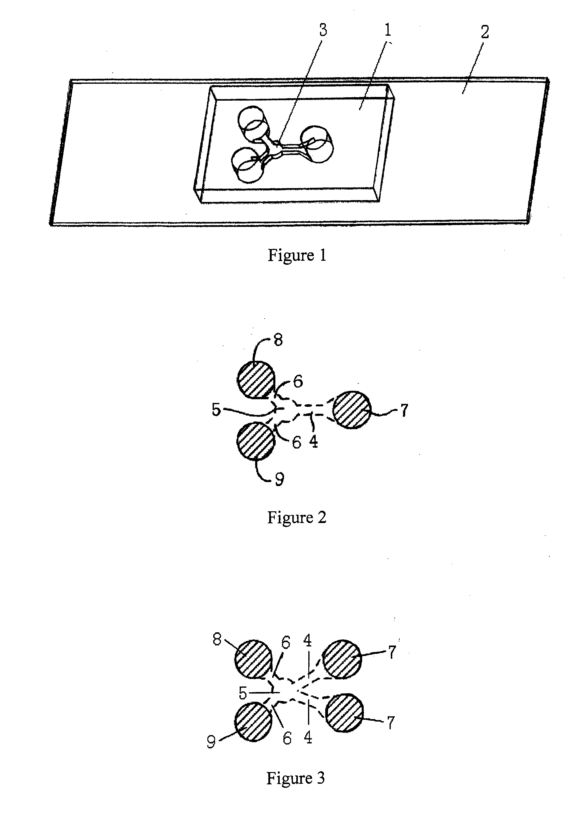
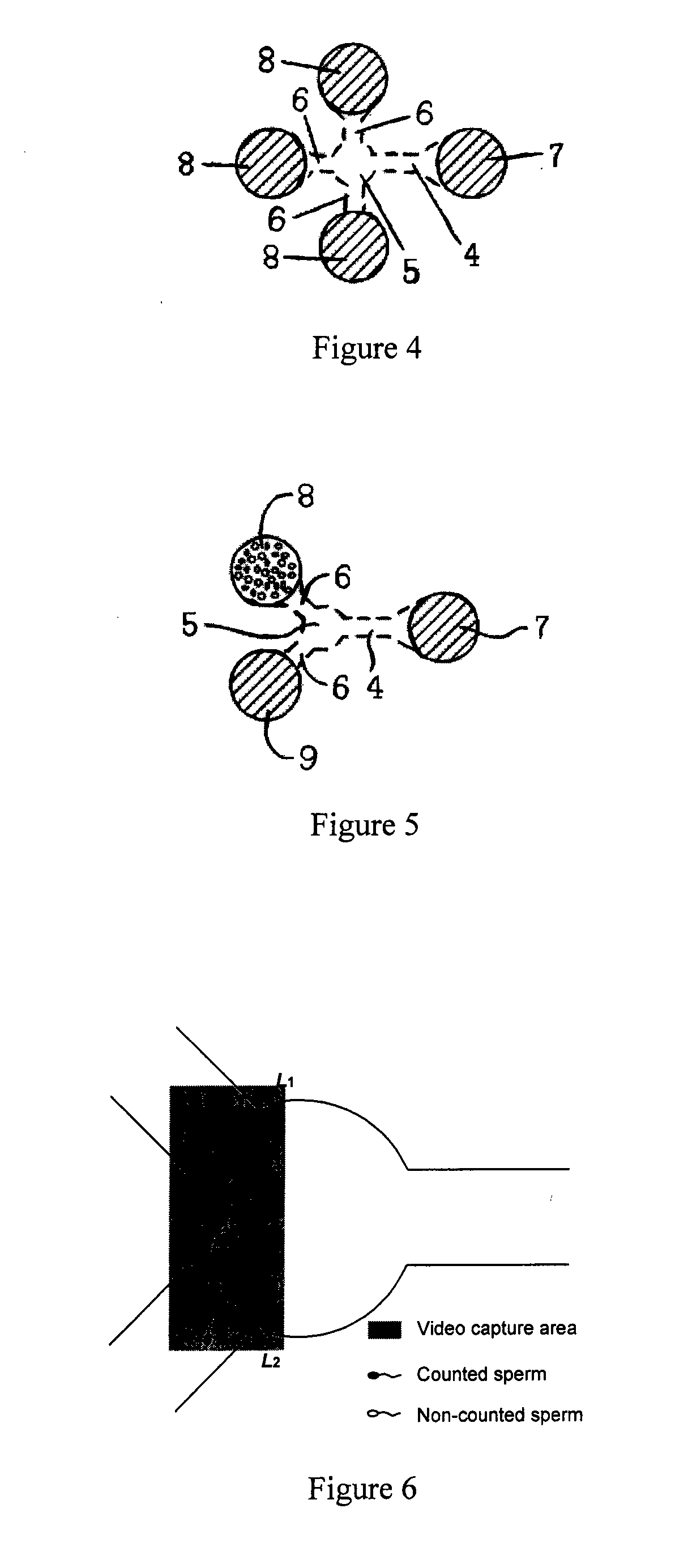
[0052]In exemplary embodiments shown in FIGS. 1 and 2, the microfluidic device includes a top layer 1 and a bottom layer 2 and the bottom layer 2 is connected closely to the top layer 1. The top layer 1 contains the microfluidic channel 3 which includes one motility screening channel 4, one buffering chamber 5 and two straight branching channels 6 symmetrically distributed around the buffering chamber 5. The motility screening channel 4 and the straight branching channels 6 are connected by the buffering chamber 5. The inlet pool 7 and two outlet pools 8 and 9 are contained in the top layer, corresponding to the ends of the microfluidic channel 3. The inlet pool 7 is connected to the motility screening channel 4 and the outlet pools 8 and 9 are connected to the straight branching channels 6.
[0053]The motility screening channel 4 facilitates cell selection depending on the intrinsic motility of different cells. The motile cells can be collected in the buffering cha...
example 2
Integrated Mouse Sperm Motility Screening and Chemotaxis Assay
[0056]In this exemplary embodiment, the top layer 1 is made of PDMS and the bottom layer 2 is made of glass. The microfluidic channel 3 is constructed with standard photolithography and micromolding procedures. SU-8 photoresist is patterned onto a 4 inch silicon wafer to form a master, using printed film as a photomask, and the thickness of SU-8 photoresist will be the final channel height. Liquid PDMS prepolymer solution is mixed by base and curing agent in a proportion of 10:1 and poured onto the master, cured at 72° C. for 1.5 h. The PDMS layer is then peeled off and bonded irreversibly with cover slide by oxygen plasma to form the channel. The specific procedure of plasma bonding is: vacuum the chamber for 1 min, inject oxygen flow at 0.1 MPa for 1 min, turn on the plasma power after the oxygen flow stops for 5 s. After the glow is stable for 15 s, turn the power off and ventilate. Finally, the PDMS and glass slides a...
PUM
 Abstract
Description
Claims
Application Information
 - R&D
- Intellectual Property
- Life Sciences
- Materials
- Tech Scout
- Unparalleled Data Quality
- Higher Quality Content
- 60% Fewer Hallucinations
Browse by: Latest US Patents, China's latest patents, Technical Efficacy Thesaurus, Application Domain, Technology Topic, Popular Technical Reports.
© 2025 PatSnap. All rights reserved.Legal|Privacy policy|Modern Slavery Act Transparency Statement|Sitemap|About US| Contact US: help@patsnap.com


