Apparatus and methods for optical stimulation of neural tissues

a neural tissue and optical stimulation technology, applied in the field of neural tissue stimulation, can solve the problems of poor spatial specificity, coagulation or ablation of the target tissue, easy electrical interference of the electrical stimulation, etc., and achieve the effect of minimal tissue damag

Inactive Publication Date: 2013-09-19
VANDERBILT UNIV
View PDF2 Cites 4 Cited by
  • Summary
  • Abstract
  • Description
  • Claims
  • Application Information

AI Technical Summary

Benefits of technology

The present invention has advantages over existing optical neural stimulation methods and can stimulate target neural tissue without causing significant tissue damage. The method uses a laser to absorb a specific molecule and increase the number of lasers and wavelengths available for optical stimulation. This allows for more precise and selective stimulation. The method also uses a coating or loading of target neurons with a specific molecule before stimulation and selective wavelengths that minimize damage to the tissue. Overall, this invention provides a safer and more effective means of optical neural stimulation.

Problems solved by technology

However, electrical stimulation is prone to electrical interference from the environment, high frequency artifacts associated with the electrical signal used, intrinsic damage caused by the electrodes used for stimulation themselves, population response due to the recruitment of multiple axons, which prevents simultaneous stimulation and recording of adjacent areas, and in general poor spatial specificity.
Photothermal effects result from the transformation of absorbed light energy to heat, which may lead to hyperthermia, coagulation, or ablation of the target tissue [12].
These boundaries are not strict and adjacent interaction types cannot always be separated.
Therefore, a heretofore unaddressed need exists in the art to address the aforementioned deficiencies and inadequacies.

Method used


Image

  • Apparatus and methods for optical stimulation of neural tissues
  • Apparatus and methods for optical stimulation of neural tissues
  • Apparatus and methods for optical stimulation of neural tissues

Examples


example

Biophysical Mechanism Responsible for Low-Level, Transient Optical Stimulation of Peripheral Nerve

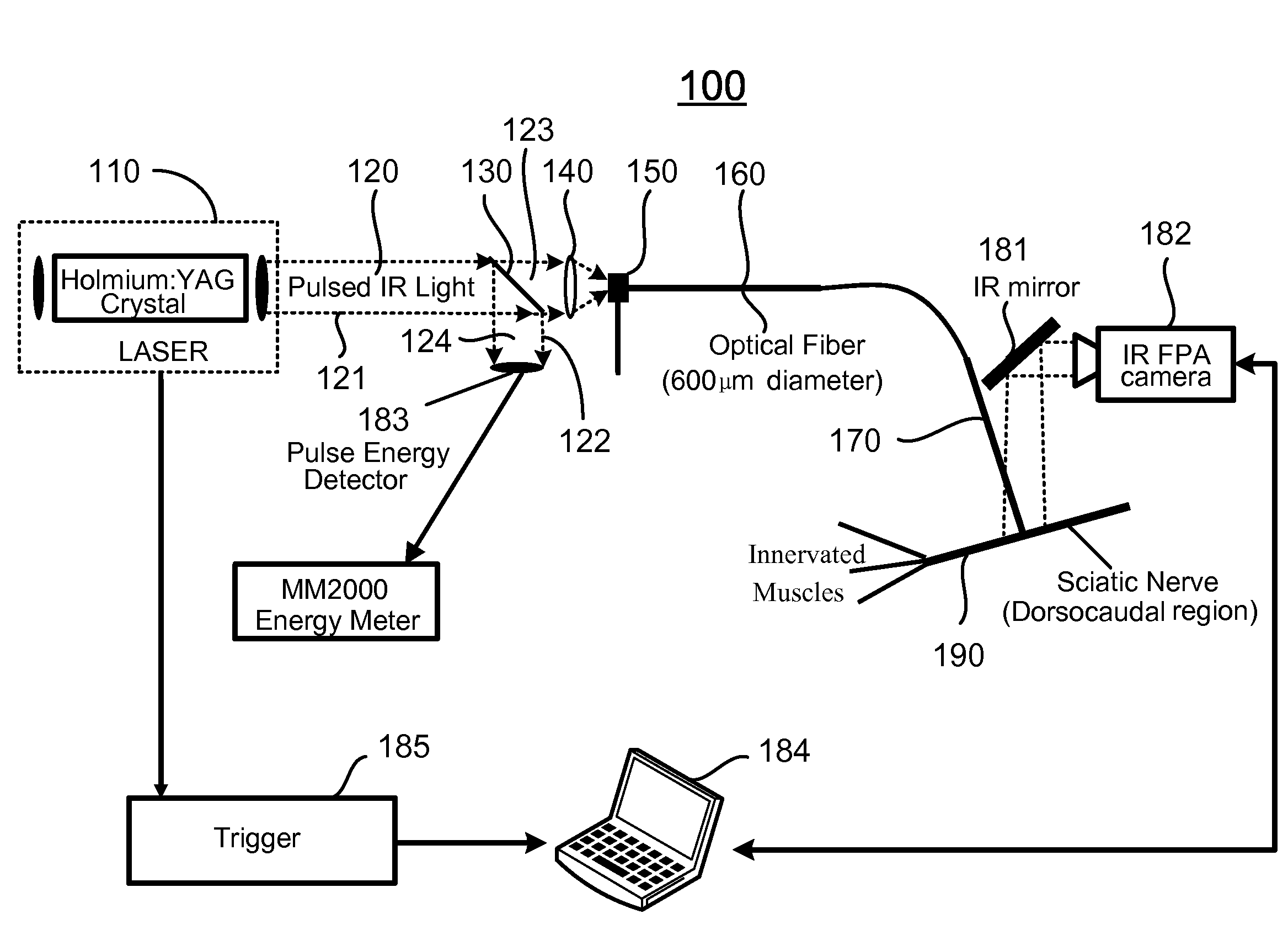
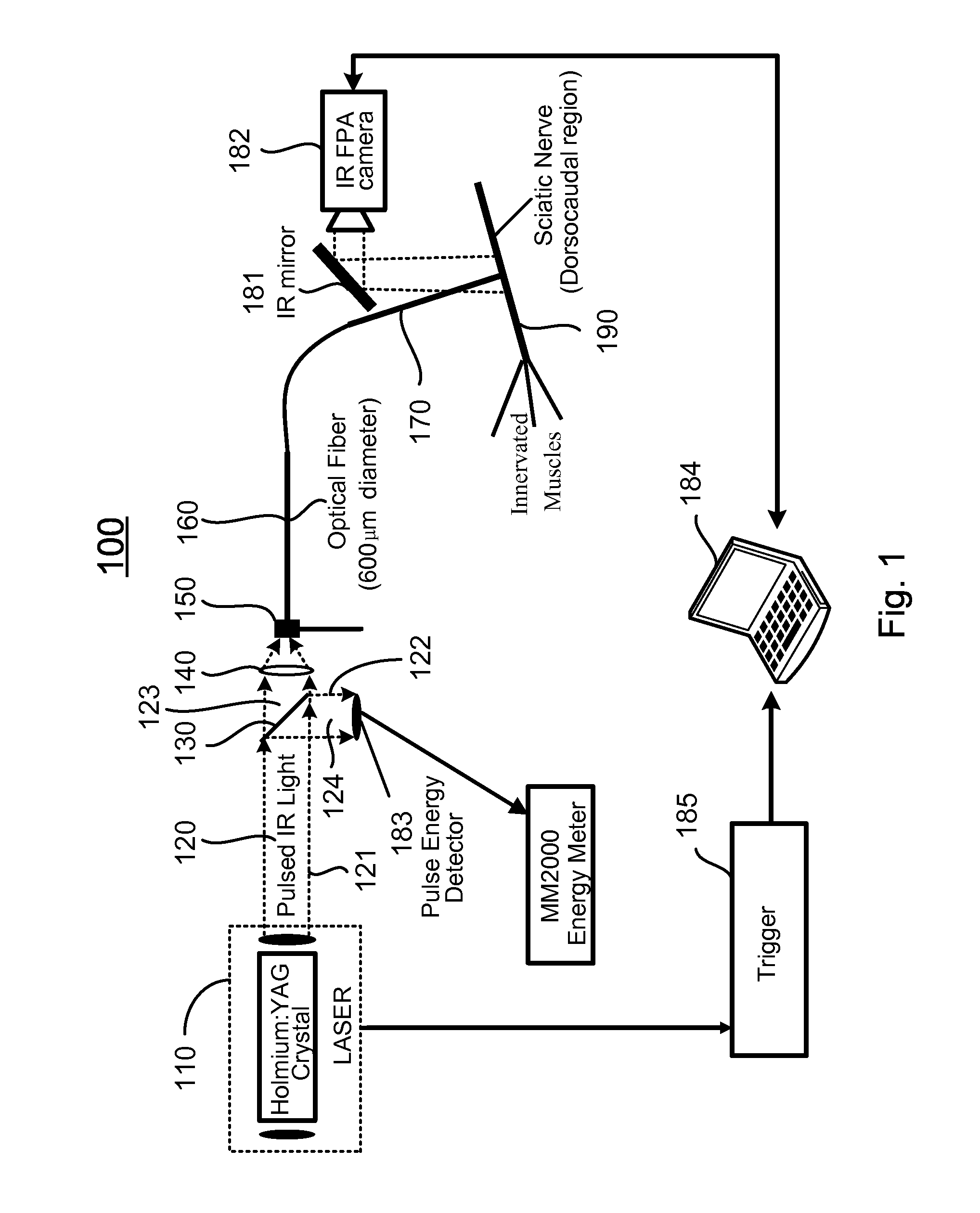
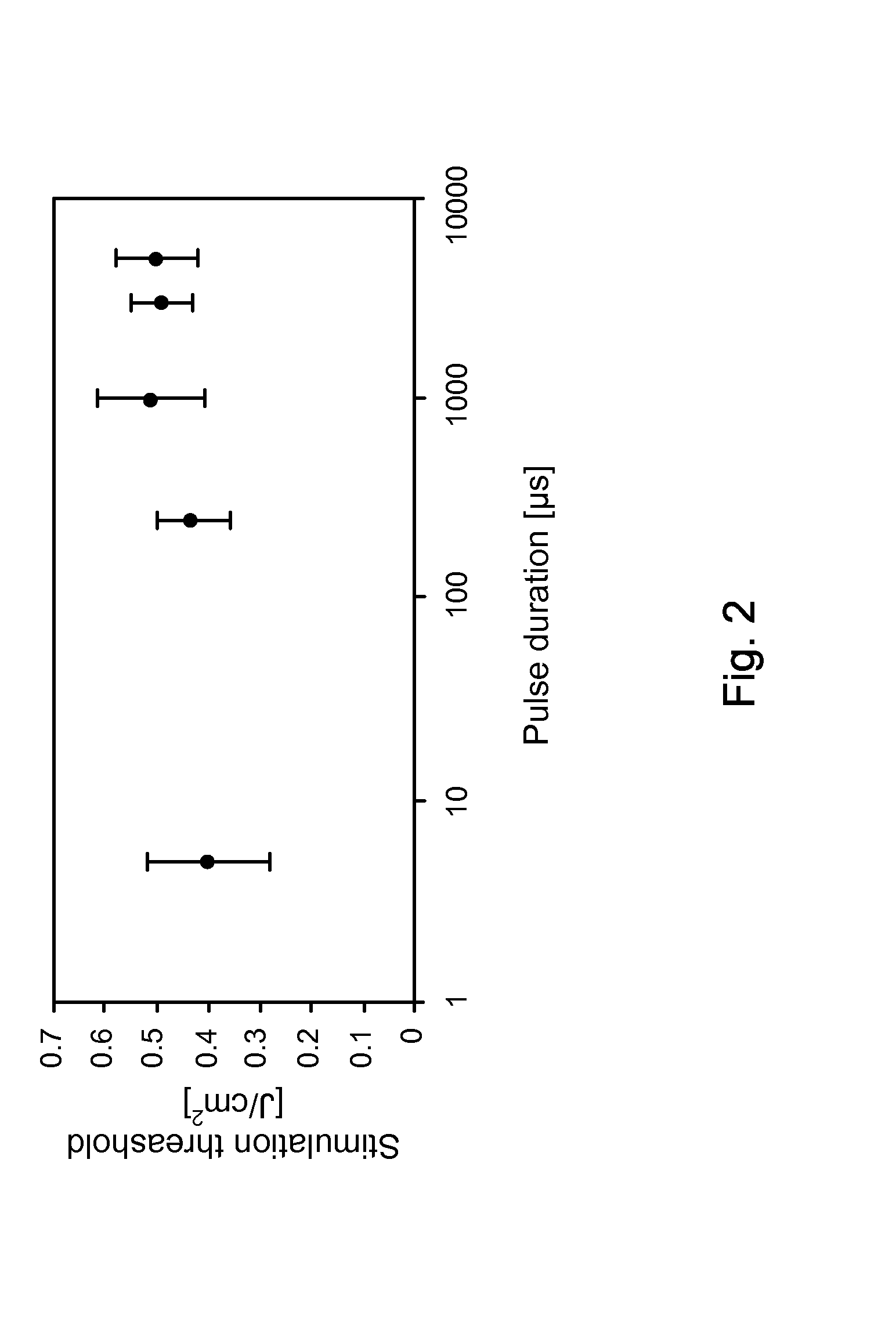
[0079]In vivo neural activation with low-levels of pulsed infrared light [1] exhibits advantages over standard electrical means by providing a contact-free, spatially selective, artifact-free stimulation method [2] that encourages development towards clinical application. In this example, the biophysical mechanism underlying this phenomenon was determined by careful examination of possible photobiological effects following absorption driven light-tissue interaction. Sciatic nerve preparation was stimulated in vivo with the Holmium:YAG laser (2.12 μm), Free Electron Laser (2.1 μm), Alexandrite laser (690 nm), and the commercial prototype solid state laser nerve stimulator built by Aculight (1.87 μm), respectively. Through a process of elimination approach, relative contributions to the neural activation were systematically determined from interaction types resulting in optical stimulatio...


PUM


Abstract

An apparatus for stimulating a neural tissue of a living subject. The neural tissue is characterized with a thermal diffusion time, Td. The apparatus includes an energy source for generating optical energy and delivering means coupled to the energy source for delivering the generated optical energy to a target neural tissue. The delivering means is configured to in operation deliver the generated optical energy with a radiant exposure that causes a thermal gradient in the target neural tissue, thereby stimulating the target neural tissue, and to deliver the optical energy in pulses with a pulse duration Tp such that Tp<Td.

Description

CROSS-REFERENCE TO RELATED PATENT APPLICATION[0001]This application is a divisional application of and claims the benefit of U.S. patent application Ser. No. 11 / 945,649, filed Nov. 27, 2007, entitled “APPARATUS AND METHODS FOR OPTICAL STIMULATION OF NEURAL TISSUES,” which is allowed and claims the benefit, pursuant to 35 U.S.C. §119(e), of U.S. provisional patent application Ser. No. 60 / 861,673, filed Nov. 27, 2006, entitled “APPARATUS AND METHODS FOR OPTICAL STIMULATION OF NEURAL TISSUES,” by Anita Mahadevan-Jansen, Jonathon D. Wells and E. Duco Jansen. The disclosure of the above applications are incorporated herein by reference in its entirety.STATEMENT AS TO RIGHTS UNDER FEDERALLY-SPONSORED RESEARCH[0002]This invention was made with government support under Contract No. FA9550-04-1-0045 awarded by the United States Department of Defense and Contract No. RO1 NS052407-01 awarded by the National Institute of Health. The government has certain rights in the invention.[0003]Some refe...

Claims


Application Information

Patent Timeline
Patent Type & Authority Applications(United States)
IPC IPC(8): A61N5/06
CPCA61N5/0622A61N5/0618
Inventor MAHDEVAN-JANSEN, ANITAWELLS, JONATHAN D.JANSEN, E. DUCO
Owner VANDERBILT UNIV
Why Eureka
Try Eureka