Interbody vertebral prosthetic and orthopedic fusion device with self-deploying anchors

a technology of vertebral prosthesis and orthopedic fusion, which is applied in the field of spinal disorders, can solve the problems of inability to achieve features, high complexity of the spinal column, and potential irritation and erosion of the great and small vessels, and achieve the effect of ease with which the device may be used

Active Publication Date: 2013-09-19
AMICUS DESIGN GRP
View PDF8 Cites 62 Cited by
  • Summary
  • Abstract
  • Description
  • Claims
  • Application Information

AI Technical Summary

Benefits of technology

[0020]One of the benefits of the embodiments of the invention is the ease with which the devices may be used. There are fewer steps as compared with conventional devices because at least one (and preferably all) of the anchors can be deployed from

Problems solved by technology

The spinal column is highly complex in that it includes all these bones and viscoelastic structures coupled to one another, housing and protecting critical elements of the nervous system having innumerable peripheral nerves and circulatory bodies in close proximity.
Additionally, the proximal end of the screws may protrude anteriorly, causing potential irritation and erosion to the great and small vessels, and possibly through innocent misadventure snag ureters and surrounding soft tissue

Method used


Image

  • Interbody vertebral prosthetic and orthopedic fusion device with self-deploying anchors
  • Interbody vertebral prosthetic and orthopedic fusion device with self-deploying anchors
  • Interbody vertebral prosthetic and orthopedic fusion device with self-deploying anchors

Examples


Embodiment Construction

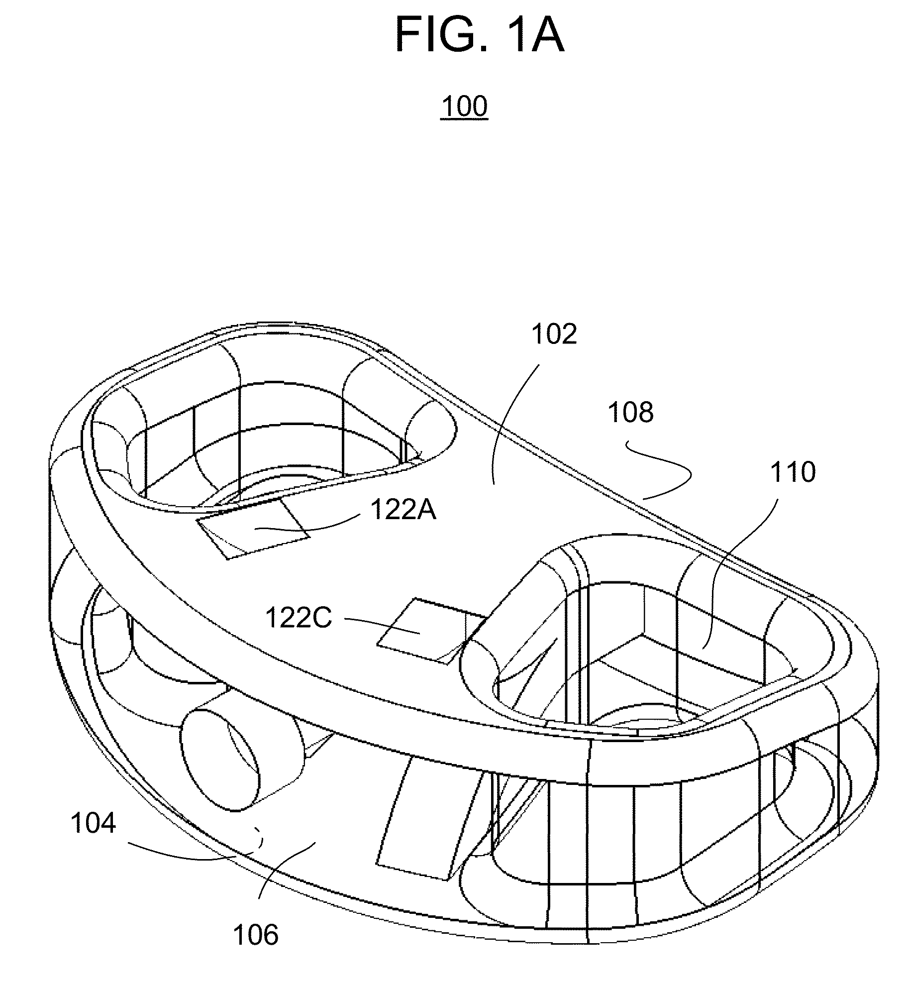
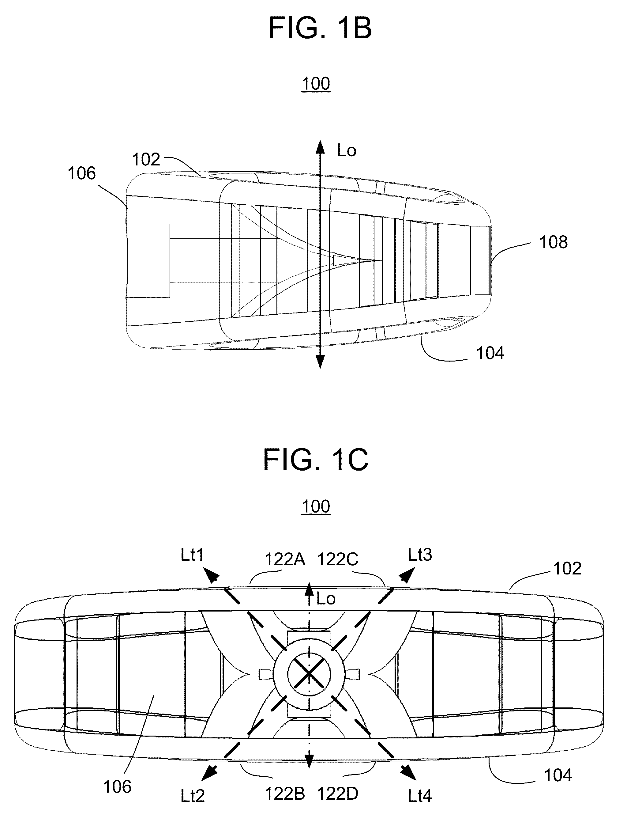
[0036]Reference is now made to FIGS. 1A, 1B, and 1C, which illustrate an intervertebral prosthetic device 100 in accordance with one or more embodiments of the present invention. FIG. 1A illustrates a perspective view of the intervertebral device 100. FIG. 1B is a lateral (side) view with the left of the drawing being in the front (anterior) direction and the right of the drawing being in the rear (posterior) direction. FIG. 1C is an anterior elevational view of the intervertebral device 100.

[0037]The body of the device may be made from any bio-compatible material, such as any of a number of biocompatible implantable polymers, including PEKK, PEKEK, polyetheretherketone (PEEK) being preferred, titanium, ceramic, etc.

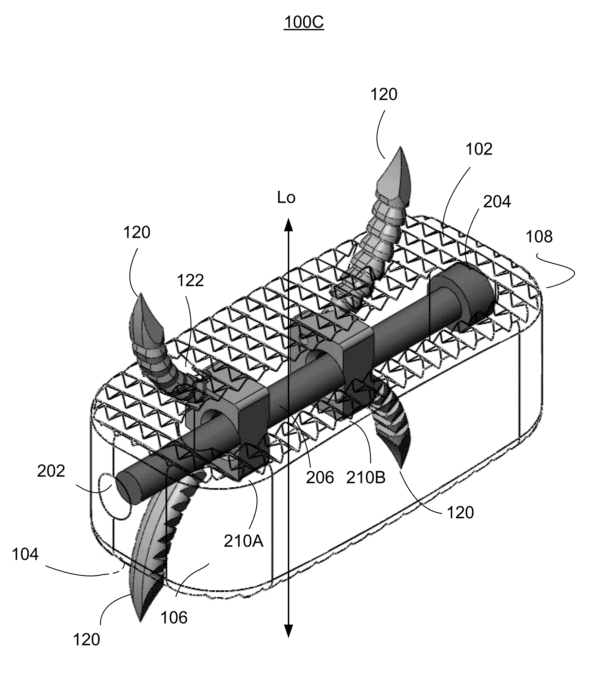
[0038]With further reference to FIG. 2, which shows the device 100 in use, the device 100 generally includes a body (or housing) that is sized and shaped to fit in the intervertebral space between adjacent vertebral bones 10, 20 of the human spine. It is understood that ...


PUM


Abstract

A prosthesis includes: a body including a first major surface for engaging an endplate of a first vertebral bone of a spine, a second major surface for engaging an endplate of an adjacent, second vertebral bone of the spine; at least one aperture extending from within the body and opening at the first major surface; at least one anchoring element disposed within the aperture and including a shaft having proximal and distal ends; and a drive mechanism engaging the proximal end of the at least one anchoring element and operating to push the at least one anchoring element out through the at least one aperture and into the first vertebral bone, without rotating the at least one anchoring element about an axis thereof.

Description

CROSS REFERENCE TO RELATED APPLICATIONS[0001]This application claims the benefit of U.S. Provisional Patent Application No. 61 / 612,423, filed Mar. 19, 2012, and U.S. Provisional Patent Application No. 61 / 756,707, filed Jan. 25, 2013, the entire disclosures of which are hereby incorporated by reference.BACKGROUND[0002]The present disclosure generally relates to apparatus and methods for treatment of spinal disorders using an intervertebral prosthesis which is disposed in an intervertebral space (or cavity) following removal of a damaged or diseased intervertebral disc. However the varied orthopedic embodiments of this apparatus and the methods used therein constitute the basic concept of the invention of fusion cages implanted throughout the human skeleton.[0003]The bones and connective tissue of an adult human spinal column consist of more than thirty three discrete bones coupled sequentially to one another by a tri-joint complex. Each tri-joint complex includes an anterior disc and...

Claims


Application Information

Patent Timeline
IPC IPC(8): A61F2/44
CPCA61F2/447A61F2/4465A61F2002/30378A61F2002/30507A61F2/4611A61F2002/30604A61F2220/0008A61F2/442A61F2002/30579A61F2/30749A61F2220/0016A61F2230/0073
Inventor LEE, RANDALL F.SAVAGE, DANIEL S.RORKE, ALAN W.GUYER, RICHARD D.ZIGLER, JACK E.
Owner AMICUS DESIGN GRP
Why Eureka
Try Eureka