Joint implant trial components

a joint implant and component technology, applied in the field of joint implant trial components, can solve the problems of clicking noise and/or vibration, and achieve the effects of reducing the width or the facilitating insertion, and reducing the width or radius of the recess

Active Publication Date: 2013-09-19
ARTHREX
View PDF4 Cites 69 Cited by
  • Summary
  • Abstract
  • Description
  • Claims
  • Application Information

AI Technical Summary

Benefits of technology

[0010]The trial component of a prosthesis preferably has an outer surface including at least one recess for interfacing with at least one groove of a joint adapter. Most preferably the at least one recess is a circumferential recess at an outer surface of the trial component, which is adapted to fit into a circumferential groove of the inner surface of the joint adapter. The trial component has at least one approximately radially oriented slit, which allows compression of the trial component for easy insertion and removal of the trial component into the joint adapter. Before inserting the trial component into the joint adapter, the trial component may be compressed, so that the width of the at least one approximately radial slit is reduced, therefore reducing the width or the radius of the recess, so it can easily be inserted into the groove of the joint adapter. The trial component may also have a ramp shaped outer surface, which allows snapping of the trial component into the joint adapter. This may result in a clicking noise and / or vibration, giving the surgeon a feedback, that the trial component has securely been locked within the joint adapter. For removal of the trial component, it is compressed, so that the width of the at least one approximately radial slit is reduced and therefore the width or the radius of the recess is reduced which allows removal of the trial component from the joint adapter. Preferably, the trial component is a liner of the joint, which may have a recessed spherical cavity. Furthermore, the trial component may be a spacer, which may be inserted between the joint adapter and the liner. In a further embodiment, the trial components may be a set of liners and spacers.
[0011]A further embodiment relates to a joint prosthesis, preferably to the humeral component of a shoulder prosthesis, although the embodiment may be applied to any other kind of prosthesis. A stem module is provided for fixing the prosthesis into the bone. A joint adapter can be attached, preferably under different angles to the stem module. The joint adapter must not necessarily be a separate part. It may also be one part with the stem module. In an alternative embodiment, the joint adapter may be directly mounted, e.g. screwed into the bone. The joint adapter holds a liner preferably having a recessed spherical cavity, which is the cup of the joint. The joint adapter has an inner surface and at least one preferably circumferential groove. The liner has an outer surface including at least one preferably circular recess. This recess preferably is concentric to the major body diameter of the liner. Its purpose is to interface with the at least one groove of the joint adapter or a spacer. Furthermore, the liner is a trial component, which has an approximately radial slit, which allows compression of the liner for easy insertion into the joint adapter or spacer and removal therefrom. This allows inserting different trial liners with different sizes thus allowing to try out different sizes to find the best size for the patient. Furthermore, an optional spacer may be inserted between the liner and the joint adapter. Like the joint adapter, the spacer has an inner surface and at least one preferably circumferential groove for interfacing with the liner. Furthermore, it has an outer surface including at least one preferably circular recess. This recess preferably is concentric to the major body diameter of the liner. Its purpose is to interface with the at least one groove of the joint adapter. Furthermore, the spacer has an approximately radial slit, which allows compression of the spacer for easy insertion into the joint adapter and removal therefrom. This allows inserting different spaces with different sizes, thus allowing to try out different sizes to find the best size for the patient. When the best sizes of the spacer and the liner have been identified a final liner and an optional final spacer without a slit may be inserted, which can no more be removed.

Problems solved by technology

This may result in a clicking noise and / or vibration, giving the surgeon a feedback, that the trial component has securely been locked within the joint adapter.

Method used


Image

  • Joint implant trial components
  • Joint implant trial components
  • Joint implant trial components

Examples


Embodiment Construction

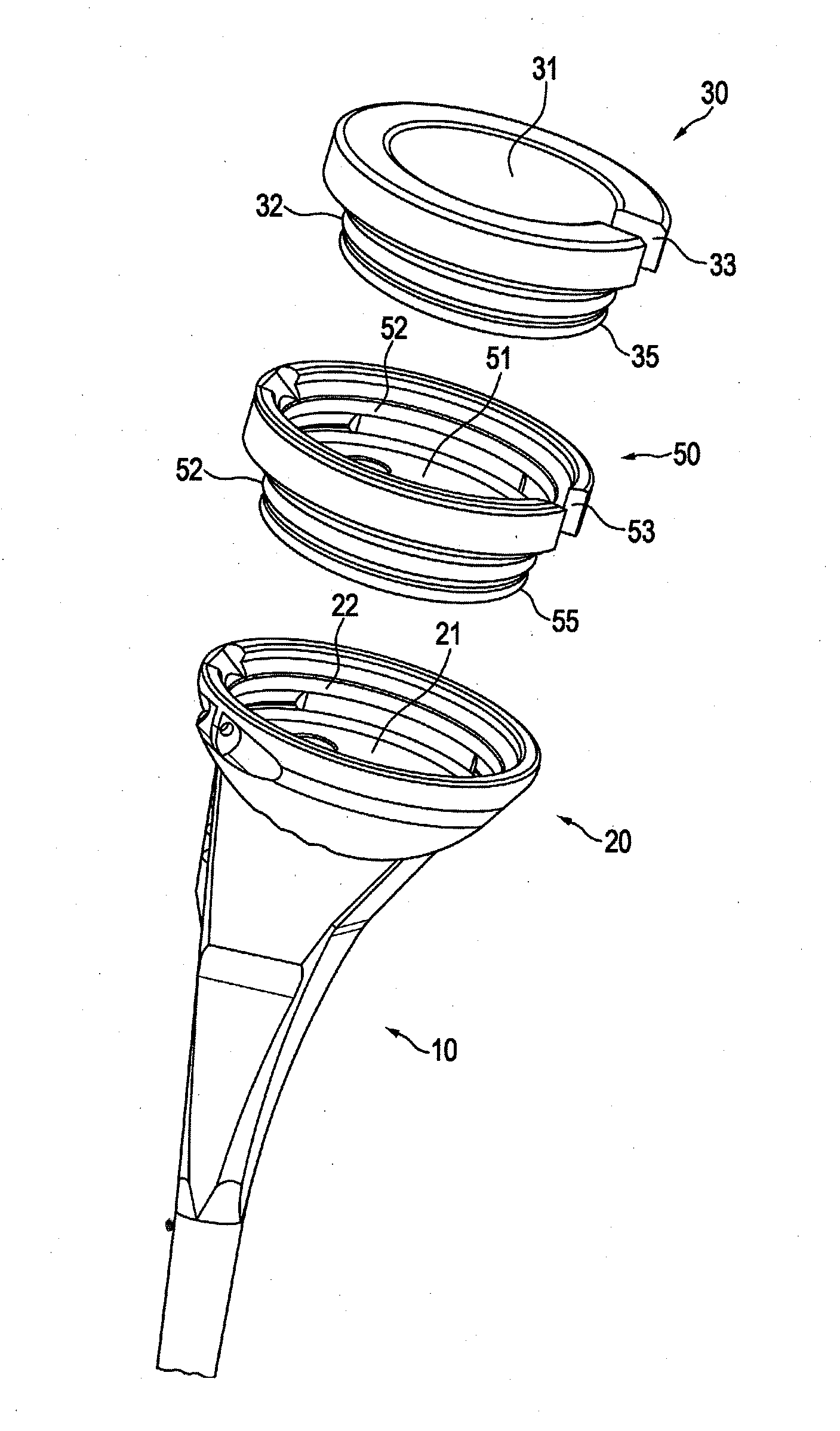
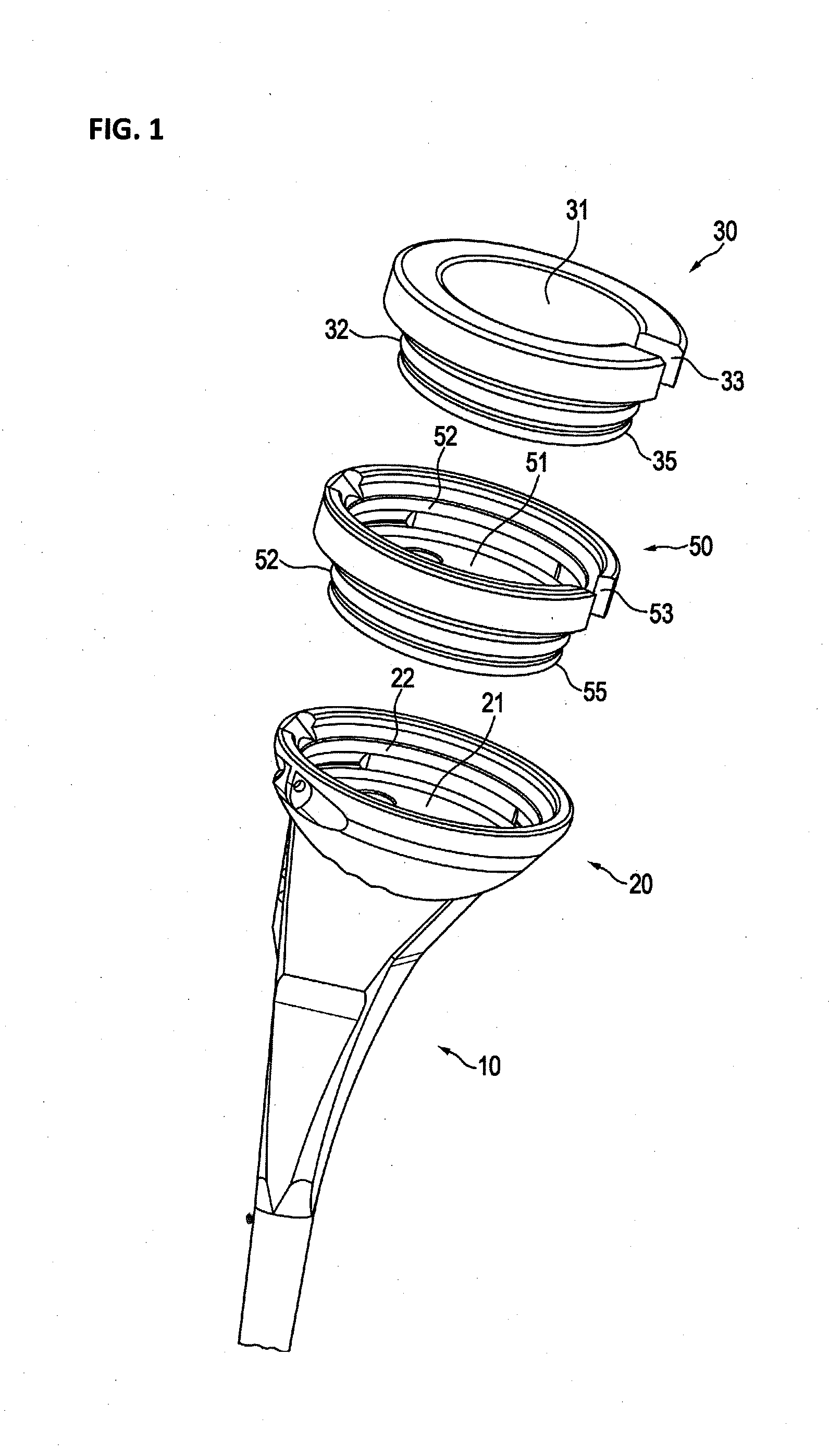
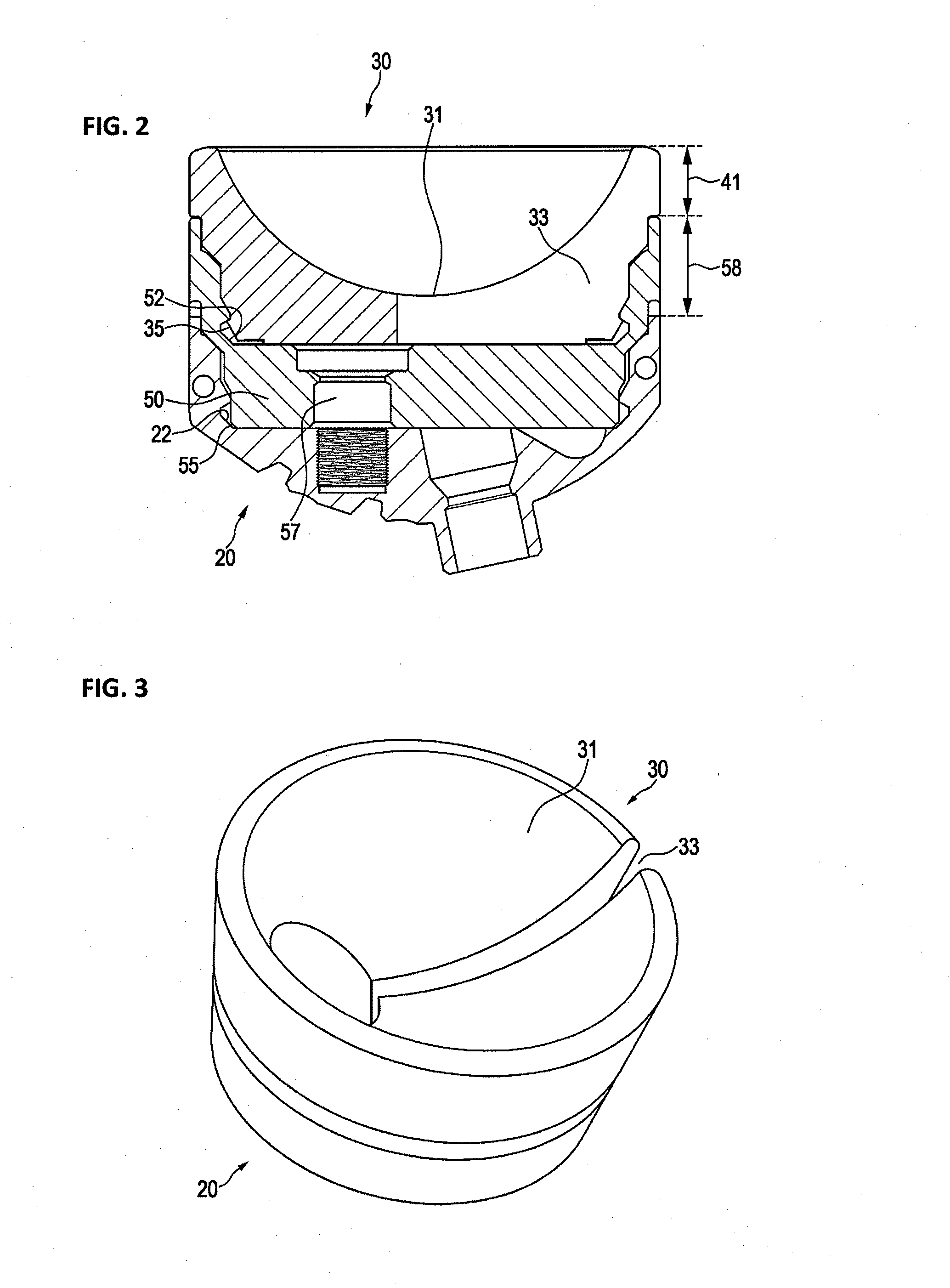
[0028]In FIG. 1, a preferred embodiment is shown. It shows the humeral component of a shoulder prosthesis, although the embodiment may be applied to any other kind of prosthesis. A stem module 10 is provided for fixing the prosthesis into the bone. A joint adapter 20 can be attached, preferably under different angles to the stem module 10. The joint adapter must not necessarily be a separate part. It may also be one part with the stem module. The joint adapter holds a liner 30 preferably having a recessed spherical cavity 31, which is the cup of the joint. The joint adapter 20 has an inner surface 21 and at least one preferably circumferential groove 22. The liner 30 has an outer surface 32 including at least one preferably circular recess 35. This recess preferably is concentric to the major body diameter of the liner. Its purpose is to interface with the at least one groove 22 of the joint adapter 20 or a spacer 50. Furthermore, the liner has an approximately radial slit 33, which...


PUM


Abstract

A humeral component of a prosthesis comprises a stem module for fixing the prosthesis into a bone. A joint adapter can be attached, preferably under different angles to the stem module. The joint adapter holds a liner having a recessed spherical cavity, which is the cup of the joint. The joint adapter has an inner surface and a circumferential groove. The liner has an outer surface including a circular recess. This circular recess preferably is concentric to the major body diameter of the liner for interfacing with the circumferential groove of the joint adapter. Furthermore, the liner has a radial slit, which allows compression of the liner for easy insertion and removal. This allows inserting different liners with different sizes thus allowing to try out different sizes to find the best size for the patient. When the best size has been identified, a final liner without a slit may be inserted.

Description

PRIORITY CLAIM[0001]This application claims priority to pending European Application No. 12159757 filed on 15 Mar. 2012.BACKGROUND OF THE INVENTION[0002]1. Field of the Invention[0003]The invention relates to trial components for joint implants and prosthesis, in particular to trial components for shoulder implants and prosthesis.[0004]2. Description of Relevant Art[0005]The shoulder joint is a ball-and-socket joint, which has an exceptional range of motion. Shoulder instability and other maladies of the shoulder joint, such as arthrosis or fracture, may require a replacement of the joint. Also, other joints other than a shoulder joint may require a replacement.[0006]A shoulder joint prosthesis, which includes the replacement of the convex head of the humerus, is disclosed in U.S. Pat. No. 7,819,923. It reflects the orientation and the center of rotation of actual joints. In the case of a worn or damaged rotator cuff or too much bone loss, such a prosthesis would not recover the ran...

Claims


Application Information

Patent Timeline
Patent Type & Authority Applications(United States)
IPC IPC(8): A61F2/40
CPCA61F2/40A61F2/4059A61F2/4684A61F2002/30331A61F2002/30367A61F2002/4641A61F2002/3055A61F2002/30594A61F2002/30616A61F2002/4022A61F2002/4062A61F2002/305
Inventor METCALFE, NICK
Owner ARTHREX
Why Eureka
Try Eureka