Glow plug

a technology of glow plugs and o-rings, which is applied in the direction of incandescent ignition, combustion process, lighting and heating apparatus, etc., can solve the problems of difficulty in providing a space for accepting deformation of compressed o-rings, failure to ensure gastightness, and breakage of o-rings

Inactive Publication Date: 2013-09-26
NGK SPARK PLUG CO LTD
View PDF2 Cites 6 Cited by
  • Summary
  • Abstract
  • Description
  • Claims
  • Application Information

AI Technical Summary

Benefits of technology

[0013]For example, even in the case where the first axis of the metallic shell and the axis of the center shaft fail to coincide with each other, when the contact member is disposed between the center shaft and the inner circumferential surface of the axial bore, the taper portion can guide the contact member toward the center of the axial bore. Therefore, misalignment between the first axis and the axis of the center shaft can be corrected via the contact member. By specifying that the outside diameter of the rear trunk portion be greater than the inside diameter of the contact member, in attachment of the contact member to the glow plug, first, the contact member can be brought into contact with the axial bore in a condition that the inside diameter of the contact member is expanded by the shoulder portion. Then, in a state in which the contact member is in contact with the center shaft (i.e., in a state in which a big gap is not formed between the contact member and the center shaft), the outside diameter of the contact member is narrowed along the taper portion; thus, the contact member is free from inward dragging and, thus, free from twist along the circumferential direction and wrinkling. Therefore, the contact member can be reliably in contact with the inner circumferential surface of the axial bore and with the outer circumferential surface of the center shaft, whereby gastightness through the axial bore can be reliably established.
[0014]In the present embodiment, the contour of the contact member may further comprise a third contour segment which is connected, at one end, to the second contour segment; which extends radially outward from the one end toward the other end thereof while extending along the second axis; which is connected, at the other end, to the first contour segment; and whose point of connection to the first contour segment is an end of the contact member with respect to the extending direction of the second axis. In attachment of the contact member to the glow plug, the contact member first comes into contact with the shoulder portion. At the time of this contact, first, the third contour segment, which extends radially outward while extending along the second axis, comes into contact with the shoulder portion. Thus, friction of the contact member against the shoulder portion is small, so that the contact member can be prevented from being caught by the shoulder portion and dragged inward.

Problems solved by technology

However, in the configuration in which the three contact surfaces of the inner circumferential surface, the center shaft, and the insulation member surround the O-ring, difficulty is encountered in providing a space for accepting deformation of a compressed O-ring.
Accordingly, the O-ring is deformed in such a manner as to enter a narrow gap between the contact surfaces; thus, internal stress in a deformed portion of the O-ring increases, potentially resulting in breakage of the O-ring.
Accordingly, the O-ring fails to maintain sufficient close contact with the contact surfaces; thus, a clearance is formed therebetween, potentially resulting in a failure to ensure gastightness.
In the process of assembling a glow plug, when the O-ring is to be disposed in a narrow gap between the center shaft and the inner circumferential surface of the axial bore, there has been involved the risk of twist of the O-ring along the circumferential direction.
Joint use of an axially long tube-like vibration insulating rubber or the like encounters difficulty in disposition between the center shaft and the inner circumferential surface of the axial bore and increases cost.

Method used


Image

  • Glow plug
  • Glow plug
  • Glow plug

Examples


Embodiment Construction

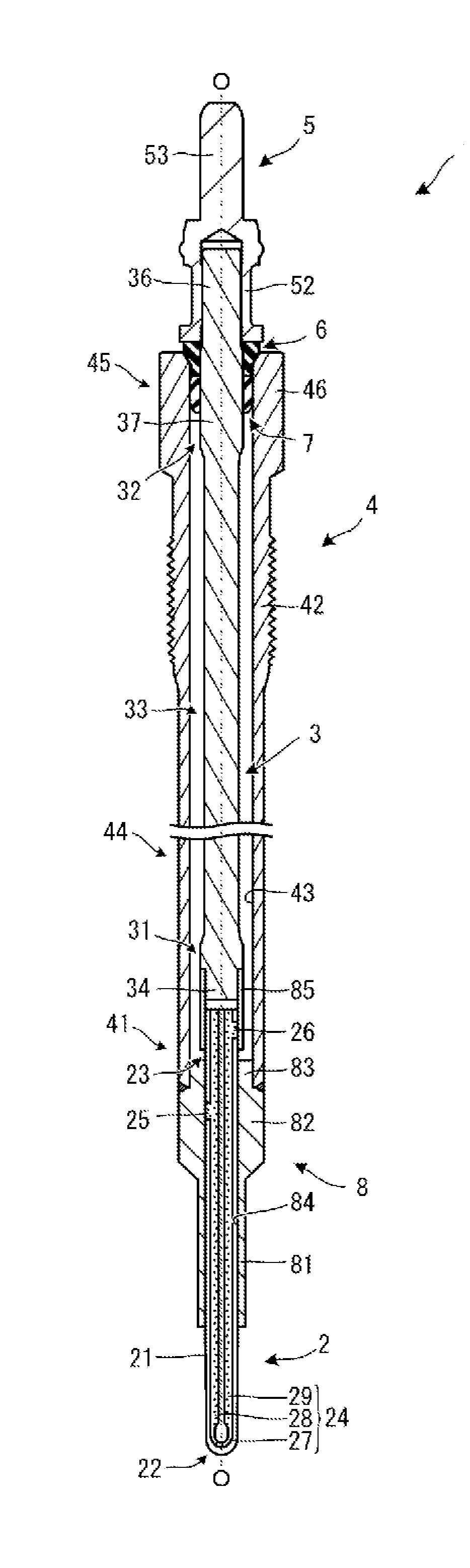
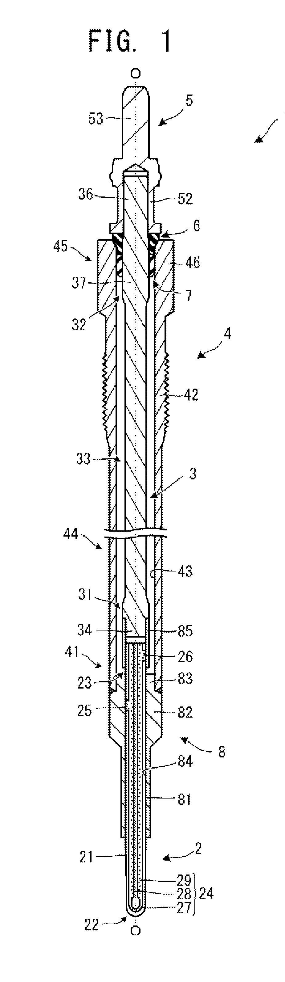
[0024]A glow plug according to an embodiment of the present invention will next be described with reference to the drawings. The entire structure of a glow plug 1 is described, by way of example, with reference to FIGS. 1 and 2. The drawings referred to herein are used for explaining technical features which the present invention can employ, and the configuration, etc., of the glow plug appearing in the drawings are given by way of illustration and not of limitation. In the following description, the axis of a metallic shell 4 is referred to as the axis O, and the axis O serves as reference in describing the positional relationship, orientations, and directions of those component members of the glow plug 1 which are attached to the metallic shell 4. With respect to the extending direction of the axis O (hereinafter, may be referred to as “the direction of the axis O”), a side on which a ceramic heater 2 is disposed (the lower side in FIG. 1) is referred to as the forward side of the...


PUM


Abstract

A glow plug (1) including a heater (2), a metallic shell (4) assuming the form of a tube having an axial bore, a center shaft (3) and a contact member (7). The contact member (7) is configured such that a contour (70) of a cross section (75) includes a second contour segment (71) in the form of a straight line, a first contour segment (72) in the form of a curve swelling radially, and third contour segments (73) in the form of curves connecting the second contour segment (71) and the first contour segment (72).

Description

TECHNICAL FIELD[0001]The present invention relates to a glow plug used for assisting in start-up of a diesel engine.BACKGROUND ART[0002]A glow plug used for assisting in start-up of a diesel engine is such that a heater which has a heat-generating resistor at its forward end portion is held directly or indirectly at a forward end portion of a tubular metallic shell having an axial bore. A rodlike center shaft is inserted into the axial bore of the metallic shell and disposed in a condition electrically insulated from the metallic shell. One end portion of the center shaft is connected to a rear end portion of the heater, and the other end portion projects from the rear end of the metallic shell. Two electrodes led from the heater are electrically connected to the metallic shell and the center shaft, respectively.[0003]In the thus-configured glow plug, in order to ensure gastightness through the axial bore of the metallic shell, an O-ring is disposed between the center shaft and the ...

Claims


Application Information

Patent Timeline
Patent Type & Authority Applications(United States)
IPC IPC(8): F23Q7/00
CPCF23Q7/001
Inventor ITO, KATSUTERUSUZUKI, HIROYUKIHATANO, GAKU
Owner NGK SPARK PLUG CO LTD
Why Eureka
Try Eureka