
Method and Apparatus for Anti-Icing and Deicing Power Transmission Lines

a technology of power transmission lines and anti-icing, which is applied in the direction of insulated conductors, cables, conductors, etc., can solve the problems of affecting the performance of these transmission lines, ice to form on these transmission lines, and undesired interruption of power flow through the power transmission system

Active Publication Date: 2013-09-26
THE BOEING CO
View PDF12 Cites 25 Cited by
  • Summary
  • Abstract
  • Description
  • Claims
  • Application Information

AI Technical Summary

Benefits of technology

The patent describes a power transmission system that manages the problem of ice forming on transmission lines. This is achieved by changing the flow of power through the lines, based on data collected from sensors and other sources, in order to prevent damage and maintain the desired level of power transmission. The system remains stable and efficient even when the flow of power is changed. Overall, the patent provides a solution for managing the issue of ice formation on power transmission lines, which can cause damage and disruption to power transmission systems.

Problems solved by technology

Consequently, weather conditions in the environment around these transmission lines may affect the performance of these transmission lines.
For example, in some situations, weather conditions may cause ice to form on these transmission lines.
However, these methods may cause an undesired interruption of power flow through the power transmission system.
Further, these methods may require more electrical energy than desired to heat the conductor to a desired temperature for anti-icing or deicing.
In some cases, a human operator may be unable to initiate the operations needed for anti-icing and / or de-icing to be performed as quickly as desired.
However, the quality of the materials used in the coating for these types of methods may decrease over time.
Further, this coating may not provide the ability to deice a transmission line once ice has adhered to the transmission line.
Additionally, these materials used for the coating may be more expensive than desired.

Method used


Image

  • Method and Apparatus for Anti-Icing and Deicing Power Transmission Lines
  • Method and Apparatus for Anti-Icing and Deicing Power Transmission Lines
  • Method and Apparatus for Anti-Icing and Deicing Power Transmission Lines

Examples


Embodiment Construction

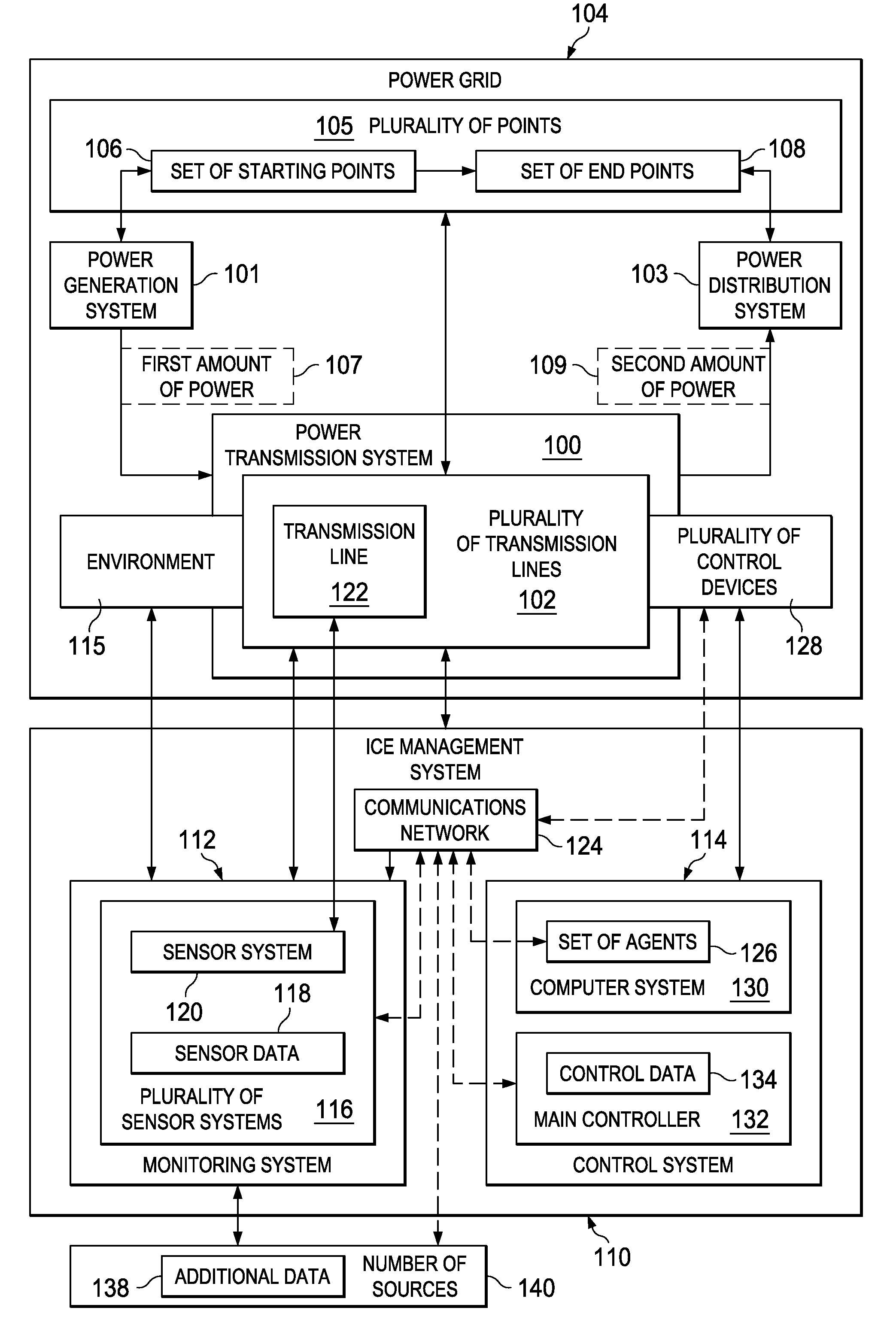
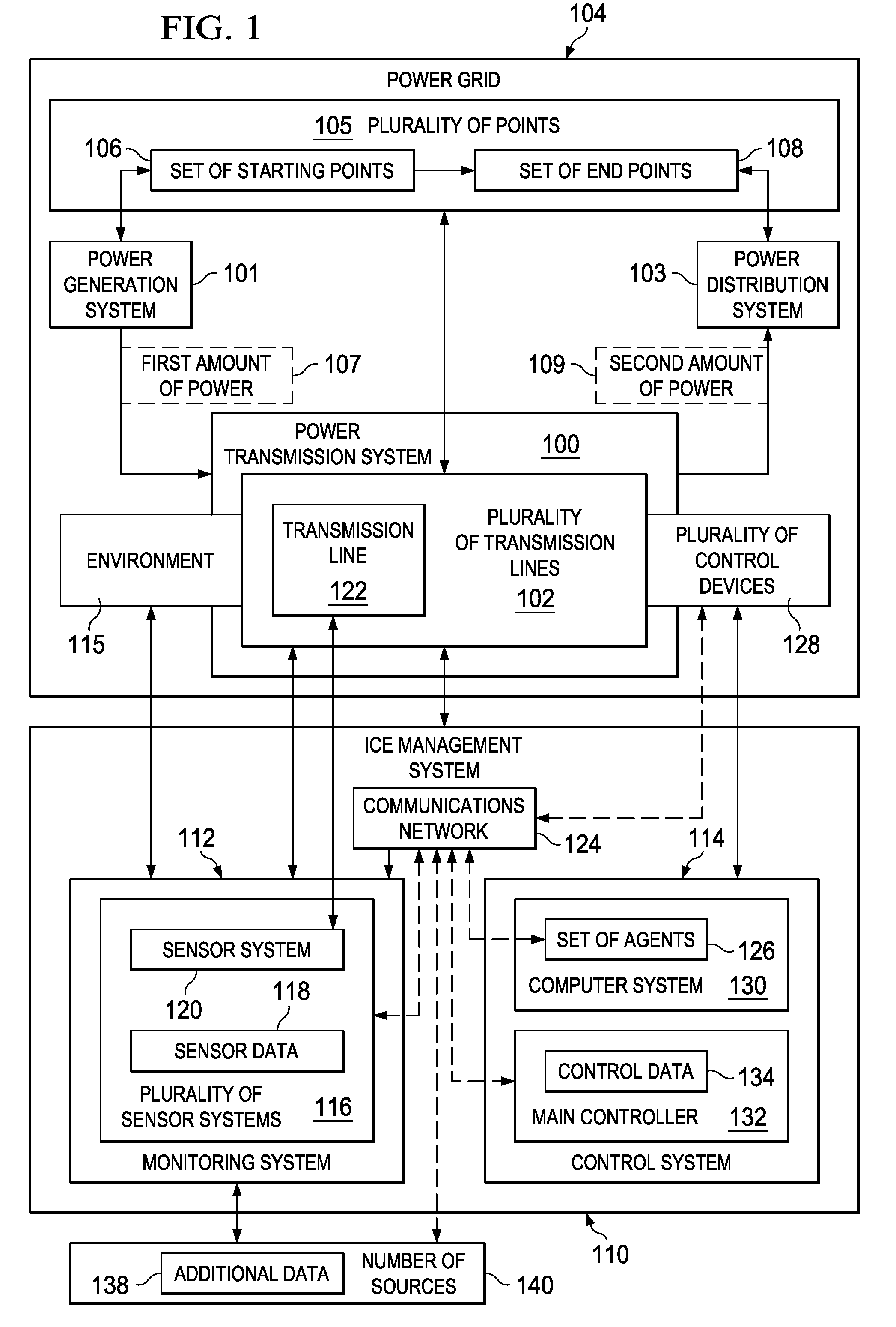
[0022]The different illustrative embodiments recognize and take into account different considerations. For example, the different illustrative embodiments recognize and take into account that some currently available methods for anti-icing and deicing transmission lines may be unable to redistribute the flow of power through a power transmission system to perform these operations without increasing the power flow into and out of the power transmission system more than desired.

[0023]Further, the different illustrative embodiments recognize and take into account that it may be desirable to have a system configured to perform anti-icing and deicing of transmission lines without using more electrical energy than desired. The different illustrative embodiments also recognize and take into account that having a system configured to perform anti-icing and deicing of transmission lines in response to substantially real-time data may be desirable.

[0024]Thus, the different illustrative embodi...


PUM


Abstract

A method and apparatus for managing icing of a plurality of transmission lines in a power transmission system. A power transmission system comprises a plurality of transmission lines and a control system. A first amount of power flows into the power transmission system through the plurality of transmission lines and a second amount of power flows out of the power transmission system through the plurality of transmission lines. The control system is configured to change a flow of power through the plurality of transmission lines such that icing of the plurality of transmission lines is managed. The first amount of power flowing into the power transmission system and the second amount of power flowing out of the power transmission system remains substantially constant after the flow of power through the plurality of transmission lines is changed.

Description

BACKGROUND INFORMATION[0001]1. Field[0002]The present disclosure relates generally to anti-icing and deicing transmission lines in a power transmission system. Still more particularly, the present disclosure relates to a method and apparatus for anti-icing and deicing transmission lines without changing the amount of power that flows into the power transmission system and the amount of power that flows out of the power transmission system.[0003]2. Background[0004]A power transmission system is configured to transfer electrical energy generated by a power generation system to a power distribution system. In some cases, a portion of the transmission lines in a power transmission system are located above ground and exposed to the air in the environment around these transmission lines. Consequently, weather conditions in the environment around these transmission lines may affect the performance of these transmission lines.[0005]For example, in some situations, weather conditions may cau...

Claims


Application Information

Patent Timeline
IPC IPC(8): H02G7/16
CPCH02J3/00H02G7/16
Inventor GAO, LIJUNSACKMAN, RONALD WARDROE, GEORGE
Owner THE BOEING CO
Features
  • Generate Ideas
  • Intellectual Property
  • Life Sciences
  • Materials
  • Tech Scout
  • Unparalleled Data Quality
  • Higher Quality Content
  • 60% Fewer Hallucinations
Learn More