Reactor and manufacturing method thereof

a technology of reactor and manufacturing method, which is applied in the manufacture of magnetic cores, transformers/inductances, magnetic bodies, etc., can solve the problems of difficult to precisely position the multiple, complex shape of the die, and complicated manufacturing procedures, so as to facilitate the manufacturing of mold cores, facilitate the insertion of core members in the die, and suppress the misposition of respective core members.

Active Publication Date: 2013-09-26
TAMURA KK
View PDF7 Cites 13 Cited by
  • Summary
  • Abstract
  • Description
  • Claims
  • Application Information

AI Technical Summary

Benefits of technology

[0019](1) it is unnecessary to bond multiple core members prior to setting of the core members in a die. Furthermore, positioning of the core members in the die can be carried out easily and precisely since only a few core members must be set in the die;
[0020](2) The resin--made mounting portions are formed by molding several core members in advance. This mounting portion regulates the position of each core member to be mounted to the divisional core later. As a result, mispositioning of the respective core members can be suppressed. This facilitates the manufacturing of the mold core including the multiple core members and spacers;
[0021](3) positioning between adjoining core members and that between each core member and spacer can be ensured highly precisely, and thus the reactor can accomplish the performance as originally designed; and
[0022](4) the leg-portion-side core members and the spacers are mounted to only the first divisional core, and thus it is not necessary to mount of the leg-portion-side core members and the spacers to the second divisional core. Accordingly, mounting can be done at once.

Problems solved by technology

Hence, when a mold core of this type is manufactured, it is necessary to set the multiple core members and spacers in a die for resin molding, and to fill a resin in the die, However, it is difficult to precisely position the multiple core members and spacers in the die, and there is a disadvantage that the core members are mispositioned, or the shape of the die becomes complex in order to suppress such a mispositioning.
According to this way, however, a bonding step of the core member with the spacer becomes necessary, and the manufacturing procedure becomes complicated.
As explained above, according to the conventional. technology, a precise positioning of each core member and spacer in a mold core is difficult.
Therefore, there is a case that the manufacturing of the mold core is difficult, or the manufactured mold core is sometimes unable to accomplish a performance as originally designed.

Method used


Image

  • Reactor and manufacturing method thereof
  • Reactor and manufacturing method thereof
  • Reactor and manufacturing method thereof

Examples


Embodiment Construction

[0026]1. Structure of Embodiment

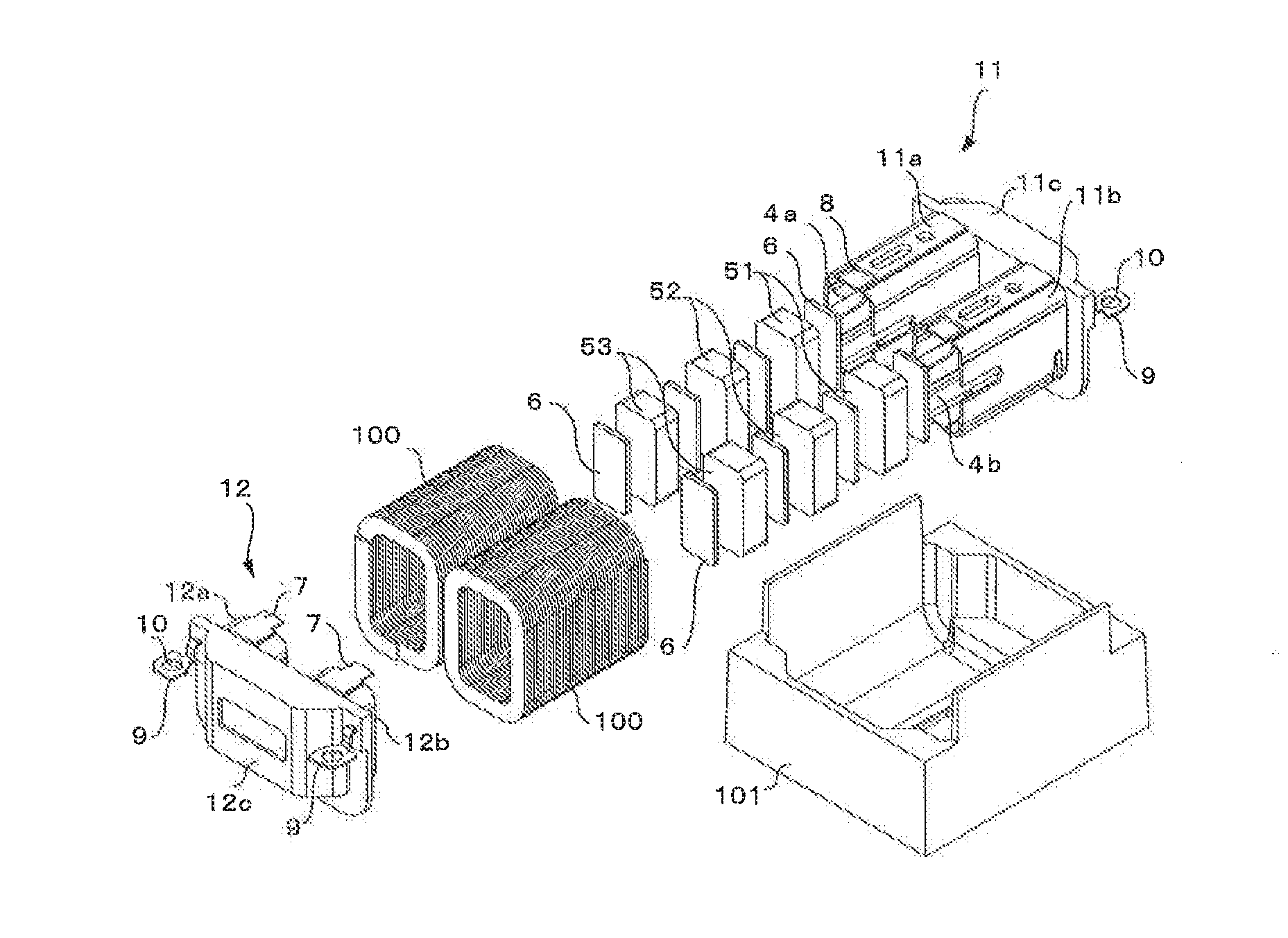
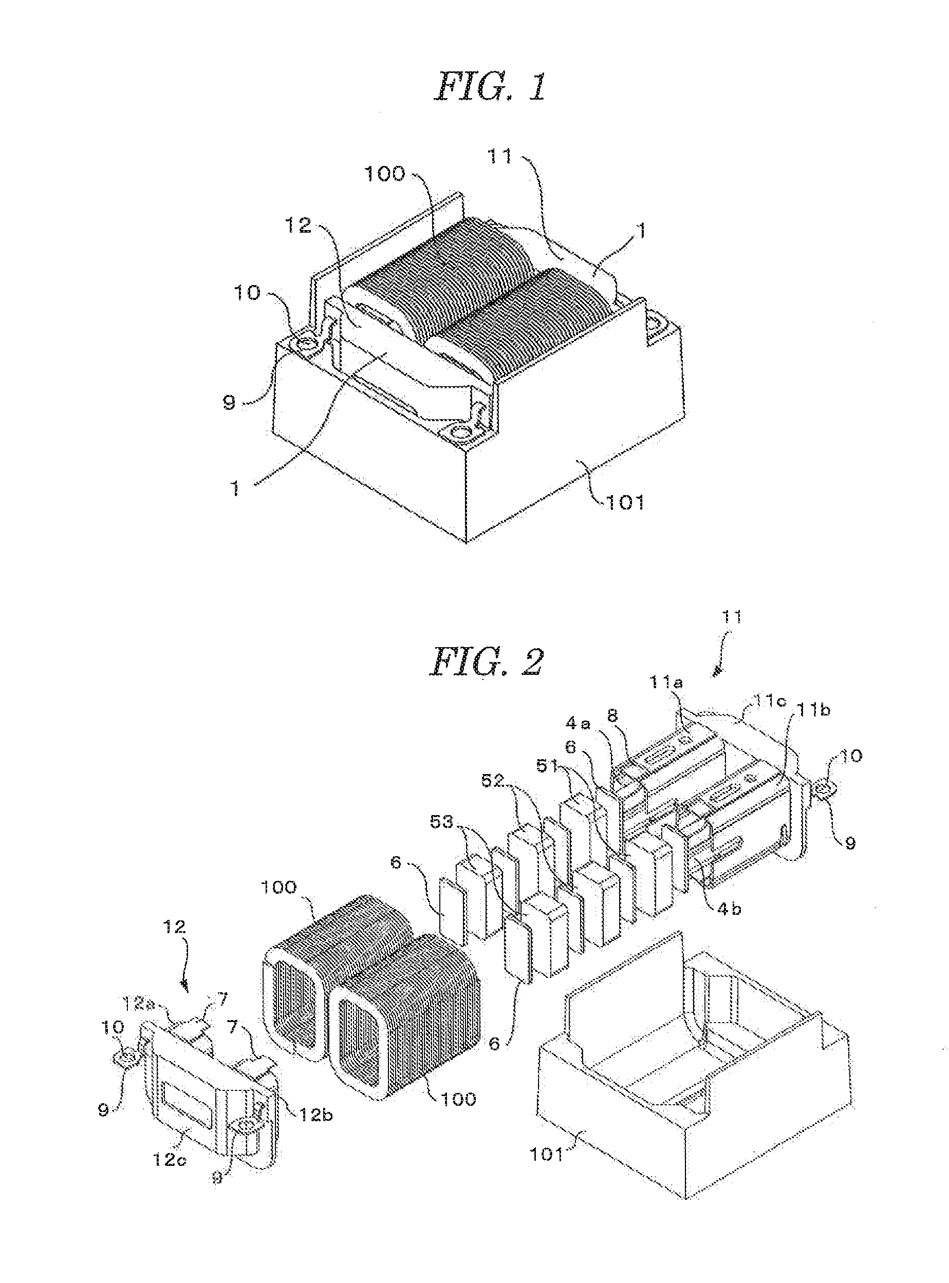
[0027]As illustrated in FIGS. 1 and 2, a reactor according to an embodiment includes a mold core 1, a coil 100 wound around this mold core 1, and a casing 101 retaining thereinside the mold core 1 and the coil 100. The mold core 1 has a first divisional core 11 and a second divisional core 12 integrated together in a manner abutting against each other and in an annular shape.

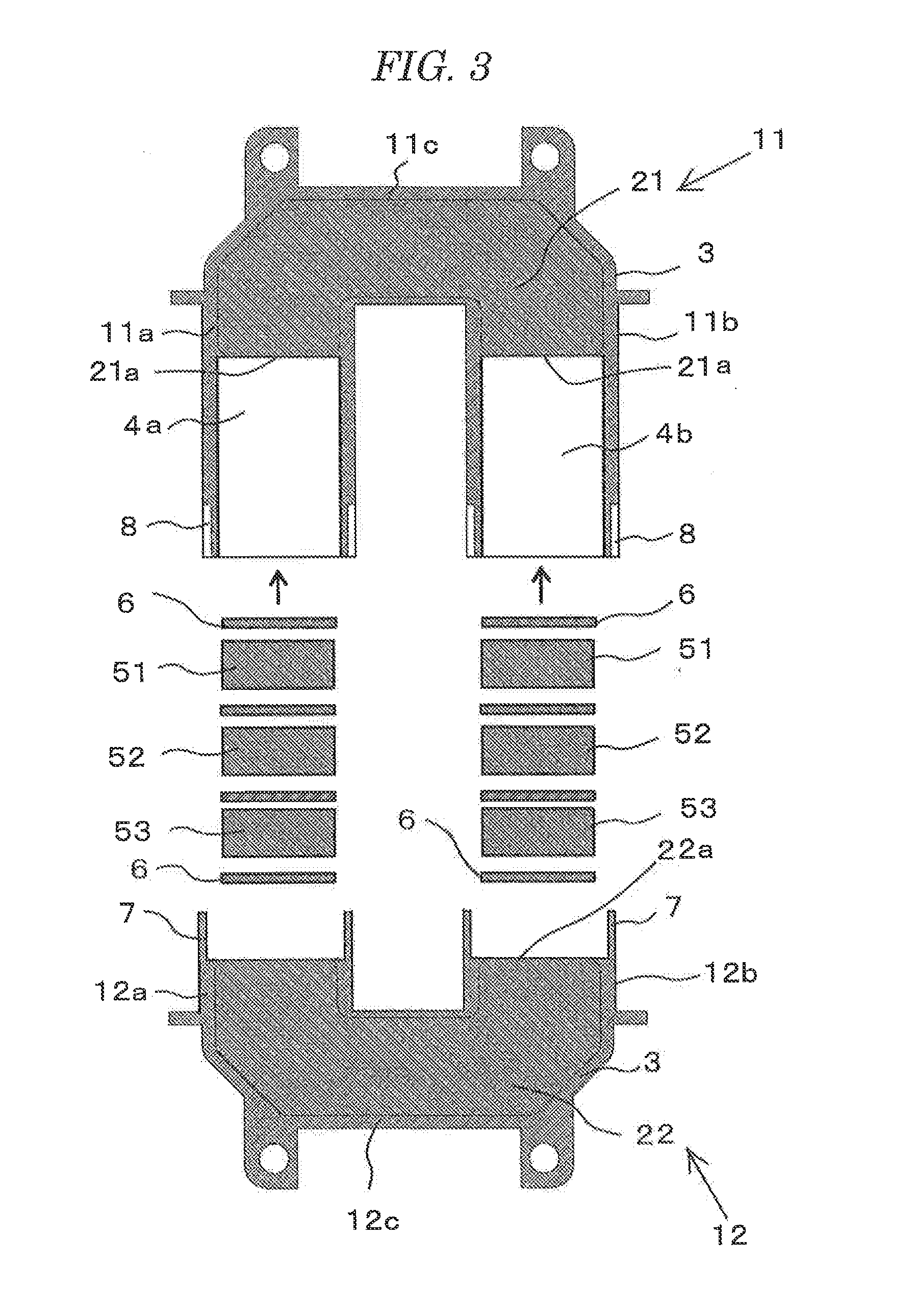
[0028]The first divisional core 11 includes right and left leg portions 11a and 11b, and a yoke 11c interconnecting those leg portions. As illustrated in FIG. 3, the first divisional core 11 is formed by molding a U-shaped first yoke-side core member 21 in a resin 3. Respective surfaces 21a of the right and left ends of the yoke-side core member 21 molded in the resin 3 are exposed at the right and left leg portions 11a and 11b of the first divisional core 11.

[0029]The right and left leg portions 11a and 11b of the first divisional core 11 are provided with cylindrical core mounti...


PUM

PropertyMeasurementUnit
outer circumferenceaaaaaaaaaa
inductanceaaaaaaaaaa
vibration resistanceaaaaaaaaaa

Abstract

First and second divisional cores each including right and left leg portions and a yoke interconnecting those together are formed by molding respective yoke-side core members in a resin. Cylindrical core mounting portions extending from the outer circumference of the surface of the yoke-side core member are formed integrally with the respective right and left leg portions of the first. divisional core. I-shaped leg-portion-side core members and spacers are attached in the cylindrical core mounting portion formed in each of the right and left leg portions. The surface of the yoke-side core member molded in the resin and the surface of the leg-portion-side core member are disposed so as to have a spacer therebetween. The two divisional cores are joined together by butting respective leg portions of the two divisional cores with each other to form an annular mold core, and a coil is wound around the mold core.

Description

CROSS-REFERENCE TO RELATED APPLICATIONS[0001]This application is based upon and claims the benefit of priority from Japanese Patent Application NO. 2012-066589, filed on Mar. 23, 2012; the entire contents of which are incorporated herein by reference.FIELD OF THE INVENTION[0002]The present invention relates to a reactor that is used for vehicles, such as an electric vehicle and a hybrid vehicle, and a manufacturing method of the reactor.DESCRIPTION OF THE RELATED ART[0003]Conventionally, a vehicular reactor is known which has a magnetic gap with a predetermined width between multiple cores in order to suppress a reduction of inductance. The reactor of this type uses an integrated core which has a spacer of ceramics or the like held in a gap between respective core members and which joins the adjoining core member and spacer by a bond.[0004]A coil is wound around the core formed in this manner, thereby structuring a reactor. In this case, a mold core which has a resin-made bobbin or ...

Claims


Application Information

Patent Timeline
Patent Type & Authority Applications(United States)
IPC IPC(8): H01F27/26H01F41/02
CPCH01F27/263H01F41/0206Y10T29/49071H01F41/005Y10T29/49075H01F37/00H01F27/02H01F27/022H01F27/2823Y10T29/49073
Inventor SUZUKI, KOTAROMAENO, KENSUKENAKATSU, RYO
Owner TAMURA KK
Why Eureka
Try Eureka