
Shielding shell

a shielding shell and shielding technology, applied in the direction of magnetic/electric field screening, electrical equipment, etc., can solve the problems of easily affecting obstructing, degrading or restricting the effective performance of the electrical circuit, and affecting the electrical circuit of the electronic equipment, so as to effectively economize material waste, effectively shielding electromagnetic interference, and convenient repair of electronic components

Inactive Publication Date: 2013-09-26
CHENG UEI PRECISION IND CO LTD
View PDF0 Cites 15 Cited by
  • Summary
  • Abstract
  • Description
  • Claims
  • Application Information

AI Technical Summary

Benefits of technology

The patent describes a cover that can be easily removed from a frame to enclose or expose electronic components without damaging the frame or cover. This cover acts as a shield to protect against electromagnetic interference and helps improve repair efficiency, saving material waste and reducing human and material cost control.

Problems solved by technology

With the wide use of electronic equipments in our daily life, electromagnetic waves are everywhere and often form a potential interference source that affects electrical circuits of the electronic equipments easily.
The electromagnetic interference may interrupt, obstruct, or otherwise degrade or limit the effective performance of the electrical circuit.
These effects can range from a simple degradation of data to a total loss of data.
However, if a repair operation needs to be performed for electronic components on the printed circuit board, it is an inevitable procedure to remove the shielding shell from the printed circuit board by damaging or disoldering the shielding shell.
As a result, not only this procedure is very inconvenient, but also the shielding shell may be easily damaged in the process of being disoldered or should be directly damaged.
So, it not only causes material waste, but also takes a long time of repair work hours, and finally fails to effectively achieve human and material cost control.

Method used


Image

  • Shielding shell
  • Shielding shell
  • Shielding shell

Examples


Embodiment Construction

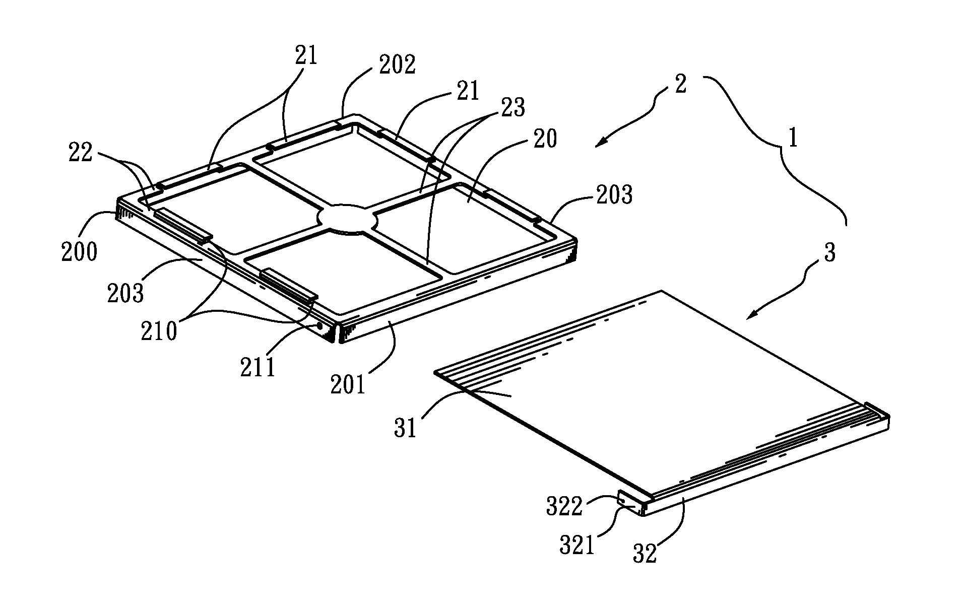
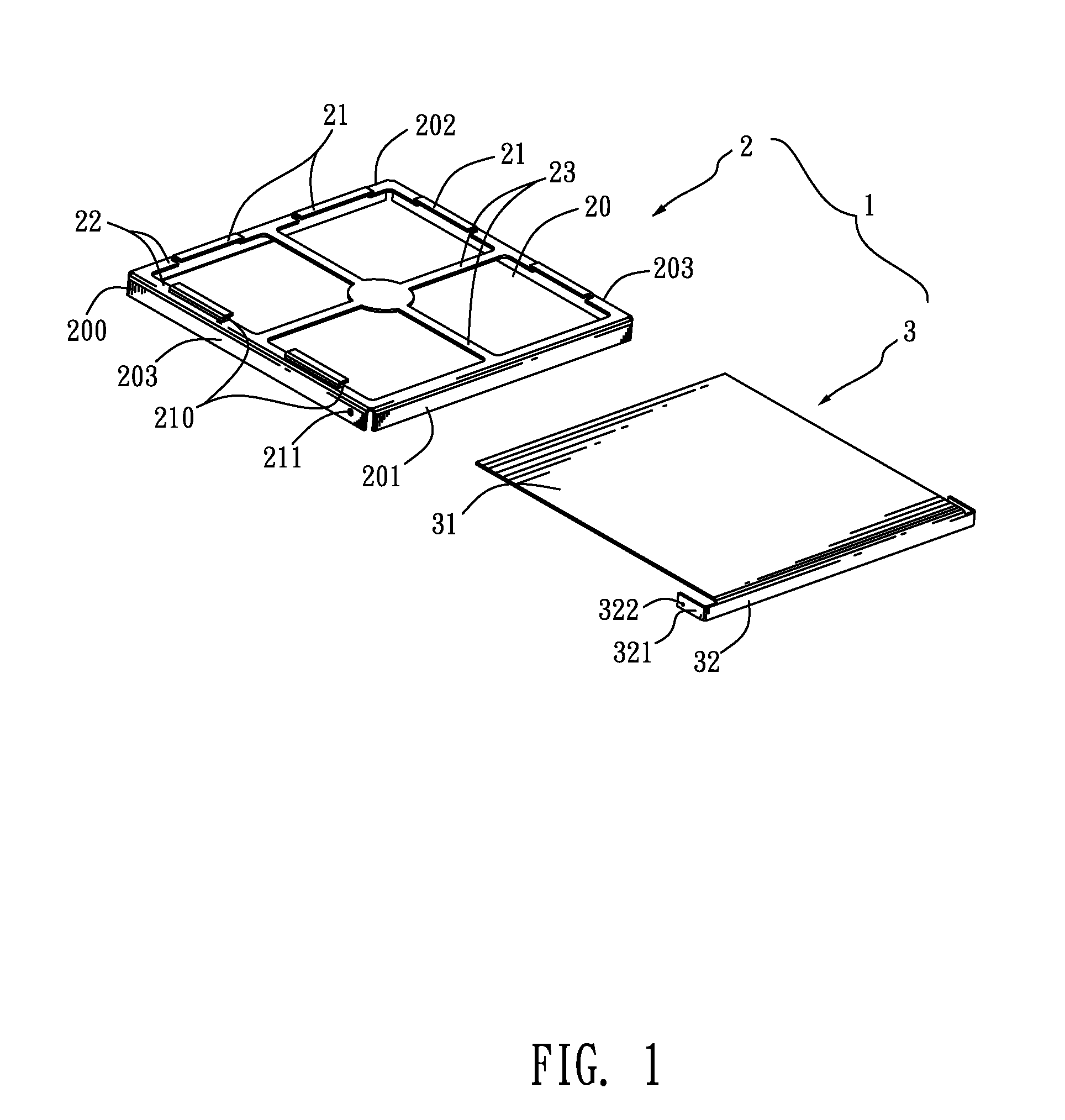
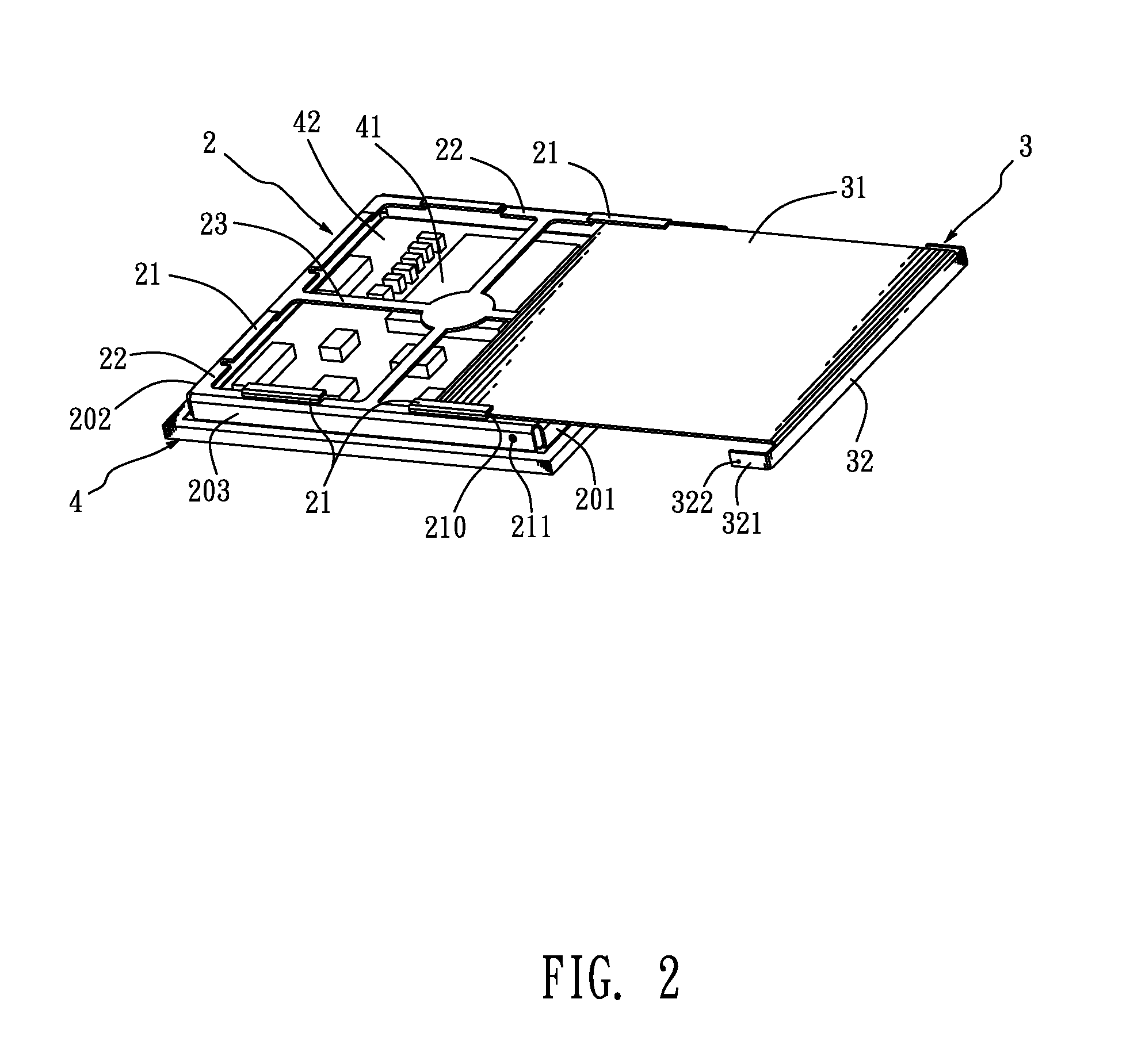
[0010]Referring to FIG. 1 and FIG. 2, a shielding shell 1 according to an embodiment of the present invention is adapted for being mounted on a printed circuit board 4 to surround electronic components 41 of the printed circuit board 4 therein for shielding electromagnetic interference. The shielding shell 1 includes a frame 2 and a cover 3.

[0011]Referring to FIGS. 1-4, the frame 2 has a ring-shaped bracket 200 with a receiving chamber 20 therein. The bracket 200 is erected on the printed circuit board 4 with the electronic components 41 located in the receiving chamber 20. A top periphery of the bracket 200 bends inward to form a support eave 22 which is parallel to a top face 42 of the printed circuit board 4 and slightly higher than the peak of the highest one of the electronic components 41. At least three restricting portions 21 of inverted-L shape protrude upward and then inward at a rear and two symmetrical sides of the top periphery of the bracket 200 respectively. An insert...


PUM


Abstract

A shielding shell includes a frame having a ring-shaped bracket with a receiving chamber therein. The bracket is erected on a printed circuit board with electronic components located in the receiving chamber. A top periphery of the bracket bends inward to form a support eave. At least three restricting portions of inverted-L shape protrude upward and inward at a rear and two symmetrical sides of the top periphery of the bracket respectively. An inserting slot is formed between the restricting portion and the support eave. A cover has a cover plate movably located on the support eave through a front of the frame and further pushed rearward to be inserted in the inserting slots so as to removably cover up the receiving chamber.

Description

BACKGROUND OF THE INVENTION[0001]1. Field of the Invention[0002]The present invention relates to a shielding shell, and more particularly to a shielding shell mounted on a circuit board for shielding electromagnetic interference.[0003]2. The Related Art[0004]With the wide use of electronic equipments in our daily life, electromagnetic waves are everywhere and often form a potential interference source that affects electrical circuits of the electronic equipments easily. The electromagnetic interference is a kind of electromagnetic phenomenon produced along with the change of electrical currents and voltages. The electromagnetic interference may interrupt, obstruct, or otherwise degrade or limit the effective performance of the electrical circuit. These effects can range from a simple degradation of data to a total loss of data. A common means of reducing the electromagnetic interference is: fixing or soldering a shielding shell on a printed circuit board for shielding the electromag...

Claims


Application Information

Patent Timeline
Patent Type & Authority Applications(United States)
IPC IPC(8): H05K9/00
CPCH05K9/0032
Inventor HOU, CHIH-YUAN
Owner CHENG UEI PRECISION IND CO LTD
Learn More