Method and apparatus for transmitting channel status information in carrier aggregation system

a carrier aggregation and channel status technology, applied in the field of wireless communications, can solve the problems of not allowing simultaneous transmission of the control region and bs failing to properly decode the data included in the data region

Active Publication Date: 2013-09-26
LG ELECTRONICS INC
View PDF13 Cites 44 Cited by
  • Summary
  • Abstract
  • Description
  • Claims
  • Application Information

AI Technical Summary

Benefits of technology

[0023]According to the present invention, even if an activation / deactivation state for a specific serving cell, i.e., a specific carrier, is erroneously recognized between a user equipment and a base station in a carrier aggregation system, the base station can correctly decode uplink data.

Problems solved by technology

On the other hand, the carrier-aggregation system (e.g., LTE-A) may or may not allow simultaneous transmission of the control region and the data region according to a configuration.
Therefore, a problem may arise in that the BS fails to properly decode the data included in the data region.

Method used


Image

  • Method and apparatus for transmitting channel status information in carrier aggregation system
  • Method and apparatus for transmitting channel status information in carrier aggregation system
  • Method and apparatus for transmitting channel status information in carrier aggregation system

Examples


embodiment 1-1

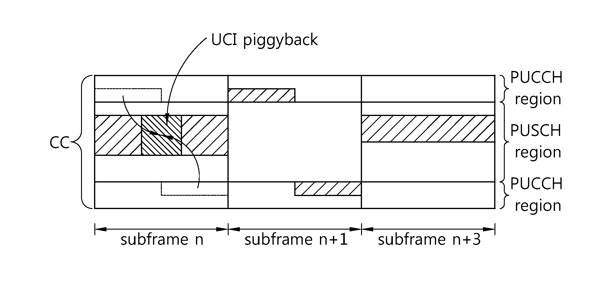
[0120]In a case where a UE is configured to transmit periodic CSI for one DL CC through a PUCCH in any subframe, a PUCCH for the CSI is not transmitted for a deactivated DL CC if PUSCH transmission does not exist in the subframe. On the other hand, if the PUSCH transmission exists in the subframe, instead of piggybacking the CSI through the PUSCH, a PUSCH resource part to be occupied, if the CSI is piggybacked on the PUSCH, can be transmitted as NULL by performing puncturing or rate matching. That is, the PUSCH transmission can be performed by not carrying a signal on a PUSCH resource to be occupied by the CSI for the DL CC or by carrying predetermined dummy bits or symbols streams. The PUSCH resource is used to transmit deactivation confirmation information in the embodiment 1, whereas the deactivation confirmation information is transmitted as NULL in the embodiment 1-1. According to the embodiment 1-1, a BS can correctly perform PUSCH decoding irrespective of whether a UE transmi...


PUM


Abstract

Provided is a channel status information (CSI) transmission method performed by a user equipment in a carrier aggregation system. The method includes: allocating a plurality of serving cells; configuring a subframe predetermined to transmit CSI for a single serving cell among the allocated plurality of serving cells; and if uplink data transmission via a physical uplink shared channel (PUSCH) region exists in the configured subframe and if the single serving cell is deactivated, transmitting deactivation confirmation information for indicating that the single serving cell is deactivated via the PUSCH region together with the uplink data.

Description

TECHNICAL FIELD[0001]The present invention relates to wireless communications, and more particularly, to a method and apparatus for transmitting channel status information of a user equipment in a carrier aggregation system supporting multiple-carrier aggregation.BACKGROUND ART[0002]In order to maximize efficiency of limited radio resources, an effective transmission and reception scheme and various methods of utilization thereof have been proposed in a broadband wireless communication system. A carrier aggregation system is one of systems considered in a next-generation wireless communication system. The carrier aggregation system implies a system which supports a broadband by aggregating one or more carriers having a bandwidth narrower than that of a desired broadband when a wireless communication system intends to support the broadband.[0003]A wireless communication system such as conventional 3rd generation partnership project (3GPP) long term evolution (LTE) uses a carrier of v...

Claims


Application Information

Patent Timeline
Patent Type & Authority Applications(United States)
IPC IPC(8): H04W72/04
CPCH04W72/0413H04L5/001H04L5/0057H04L1/1671H04W28/06H04L5/0098H04L1/0027H04L1/0026H04W24/00H04W72/21
Inventor AHN, JOON KUIYANG, SUCK CHELKIM, MIN GYUSEO, DONG YOUN
Owner LG ELECTRONICS INC
Why Eureka
Try Eureka