Fuel cell stack

a fuel cell and stack technology, applied in the field of fuel cell stacks, can solve the problems of long time required to launch the fuel cell into steady power generation, and easy heat displacement, so as to reduce the time required for starting, the effect of rapid raising of the temperature of the fuel cell and rapid distortion or deformation

Active Publication Date: 2013-09-26
HONDA MOTOR CO LTD
View PDF7 Cites 1 Cited by
  • Summary
  • Abstract
  • Description
  • Claims
  • Application Information

AI Technical Summary

Benefits of technology

[0010]The SOFC is operated at considerably high temperature. Therefore, it takes long time to launch the fuel cell into steady power generation. Therefore, it is desired to reduce the time required for starting the operation of the fuel cell. For this purpose, in particular, at the time of starting operation, the temperature of the fuel cell could be raised rapidly. However, in this case, temperature difference may occur between components or portions of the fuel cell, and rapid distortion or deformation may occur by heat displacement easily.
[0013]The present invention has been made to solve the problems of this type, and an object of the present invention is to provide a fuel cell stack which makes it possible to reliably absorb heat displacement caused by rapid increase in the temperature of fuel cells, and prevent deformation of the stack as much as possible.
[0018]In the present invention, displacement generated in the fuel cell stack can be absorbed by the displacement absorbing mechanism provided in each of the first sandwiching section, the second sandwiching section, the fuel gas supply section, and the oxygen-containing gas supply section. In the structure, rapid displacement that occurs when the temperature is raised rapidly can be absorbed effectively by the entire fuel cell stack. Therefore, generation of distortion in the stack is suppressed, and a desired current collection performance and sealing performance can be maintained suitably.

Problems solved by technology

Therefore, it takes long time to launch the fuel cell into steady power generation.
However, in this case, temperature difference may occur between components or portions of the fuel cell, and rapid distortion or deformation may occur by heat displacement easily.
In the structure, components such as the interconnectors 5a (separators) and the MEAs may be damaged undesirably.

Method used


Image

  • Fuel cell stack
  • Fuel cell stack
  • Fuel cell stack

Examples


Embodiment Construction

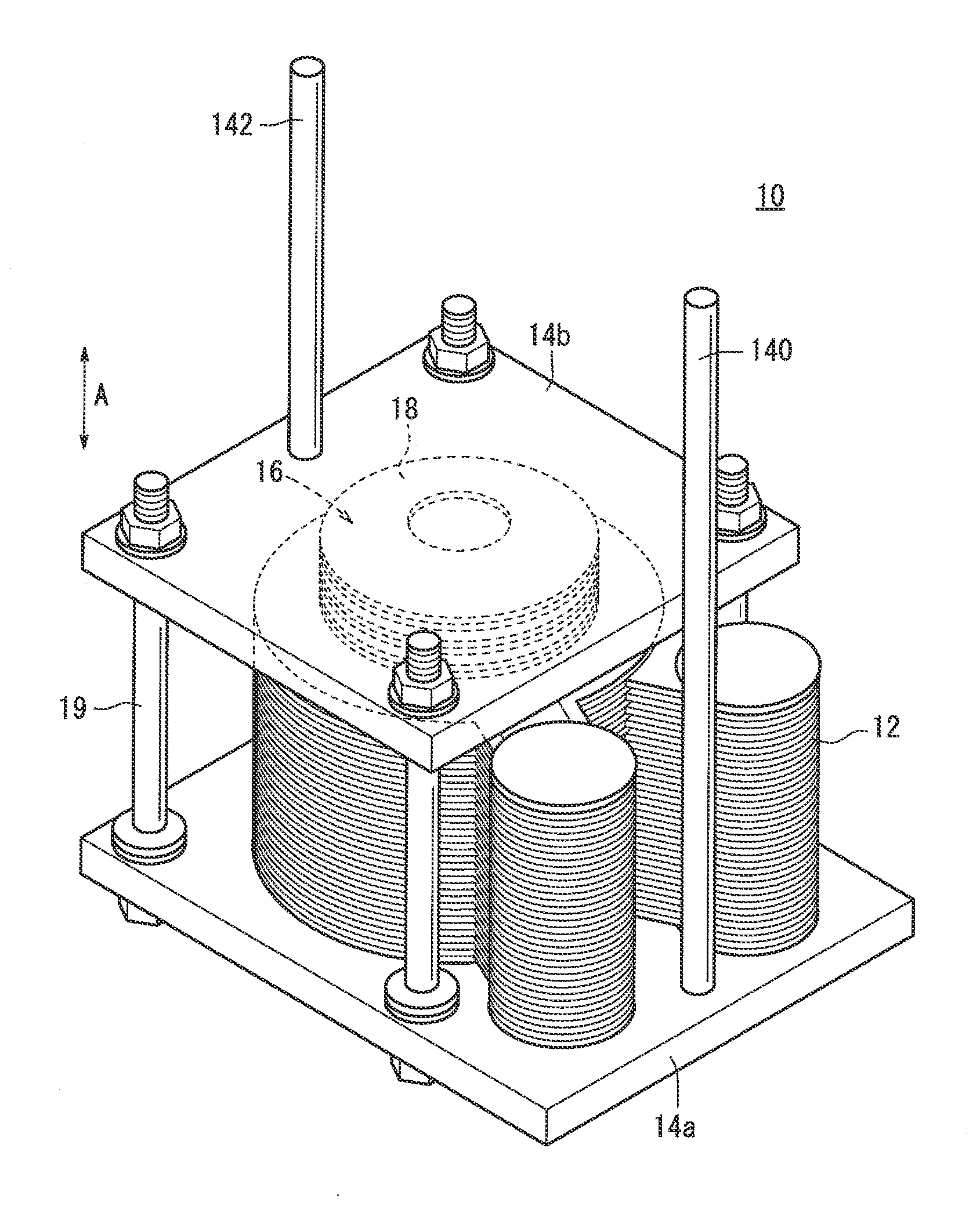
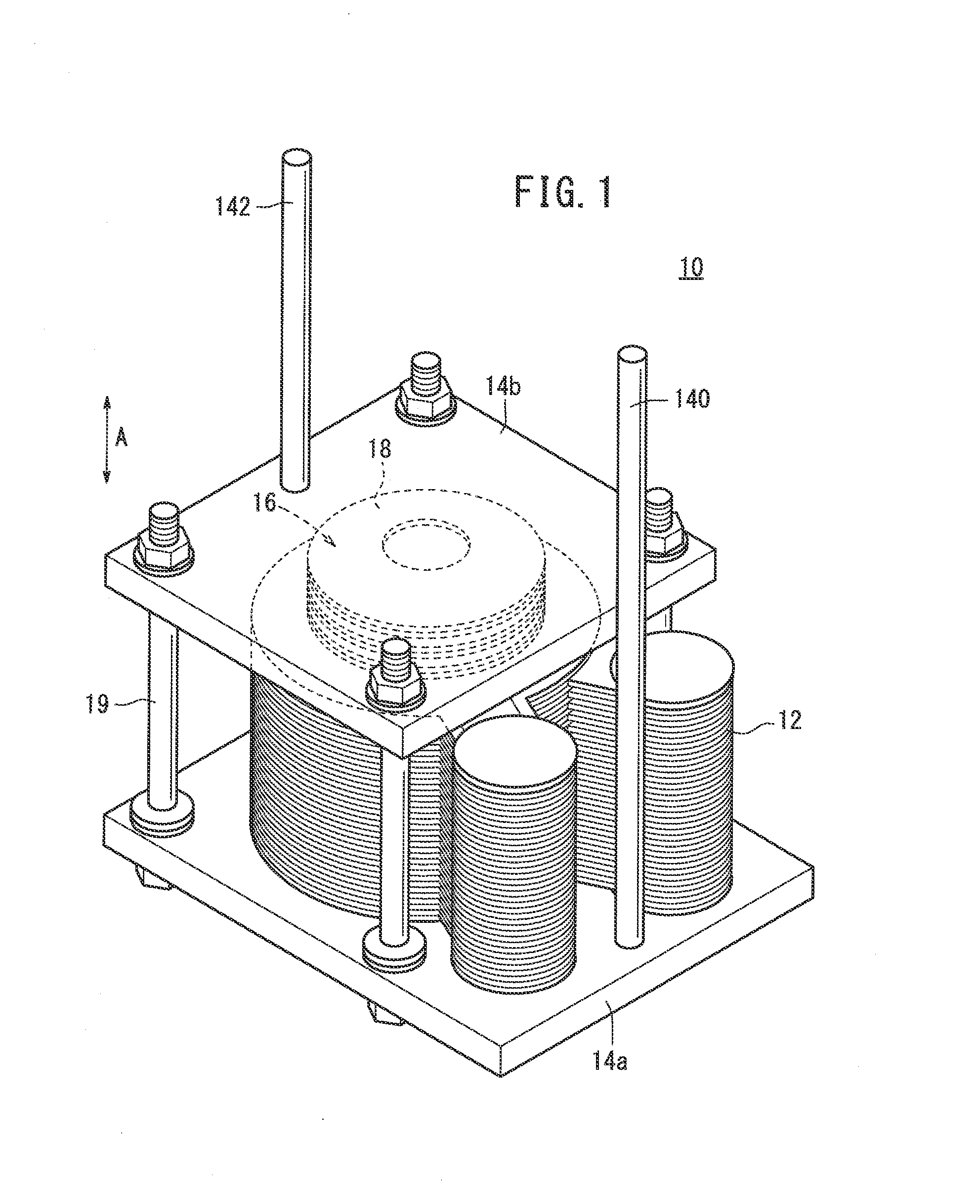
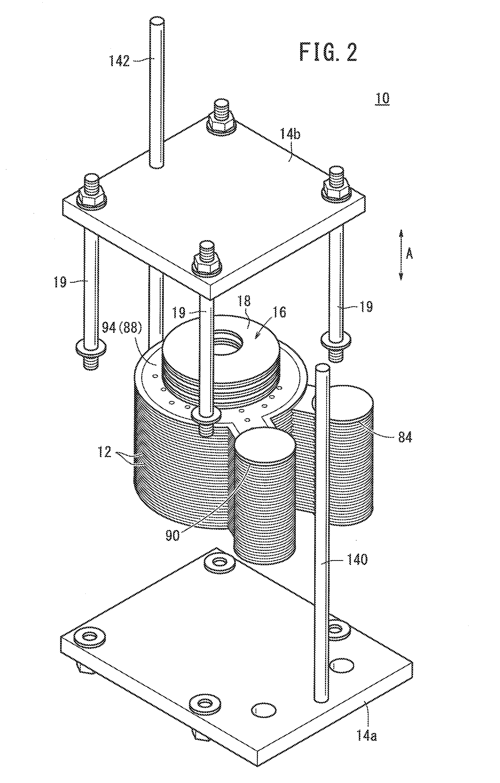
[0031]As shown in FIGS. 1 and 2, a fuel cell stack 10 according to an embodiment of the present invention comprises a stack body formed by stacking a plurality of fuel cells 12 in a direction indicated by an arrow A. The fuel cell stack 10 is used in various applications, including stationary and mobile applications. For example, the fuel cell stack 10 is mounted on a vehicle.

[0032]At one end of the fuel cell stack 10 in the stacking direction, a first plate member 14a is provided, and at the other end of the fuel cell stack 10 in the stacking direction, a second plate member 14b is provided. The second plate member 14b is smaller in size than the first plate member 14a, and as will be described later, the second plate member 14b is provided at a position corresponding to the first sandwiching sections 88 and the second sandwiching sections 94.

[0033]A spring member 18 of a load applying mechanism 16 is provided between the second plate member 14b and the first sandwiching sections 8...


PUM

PropertyMeasurementUnit
shapeaaaaaaaaaa
rigidityaaaaaaaaaa
displacement absorbing mechanismaaaaaaaaaa

Abstract

A fuel cell stack includes a first separator and a second separator. The first separator includes a first sandwiching section for sandwiching an electrolyte electrode assembly, a fuel gas supply section, and a first bridge section. A fuel gas supply passage extends through the fuel gas supply section in the stacking direction. The second separator includes a second sandwiching section for sandwiching the electrolyte electrode assembly, an oxygen-containing gas supply section, and a second bridge section. An oxygen-containing gas supply passage extends through the oxygen-containing gas supply section. A first displacement absorbing mechanism, a second displacement absorbing mechanism, a third displacement absorbing mechanism and a fourth displacement absorbing mechanism are provided in the fuel gas supply section, the oxygen-containing gas supply section, the first sandwiching section and the second sandwiching section for absorbing displacement generated in the fuel cell stack.

Description

TECHNICAL FIELD[0001]The present invention relates to a fuel cell stack formed by stacking a plurality of fuel cells. Each of the fuel cells is formed by sandwiching an electrolyte electrode assembly between a first separator and a second separator. The electrolyte electrode assembly includes an anode, a cathode, and an electrolyte interposed between the anode and the cathode.BACKGROUND ART[0002]Typically, a solid oxide fuel cell (SOFC) employs an electrolyte of ion-conductive solid oxide such as stabilized zirconia. The electrolyte is interposed between an anode and a cathode to form an electrolyte electrode assembly (MEA). The electrolyte electrode assembly is interposed between separators (bipolar plates). In use, predetermined numbers of the electrolyte electrode assemblies and the separators are stacked together to form a fuel cell stack.[0003]In the fuel cell, it is required to supply a fuel gas (e.g., hydrogen-gas) to the anode of the electrolyte electrode assembly and an oxy...

Claims


Application Information

Patent Timeline
Patent Type & Authority Applications(United States)
IPC IPC(8): H01M8/04H01M8/24
CPCH01M8/0228H01M8/0247H01M8/0258H01M8/0271H01M8/2425H01M8/2485H01M2008/1293Y02E60/50Y02E60/525H01M8/04201H01M8/2465H01M8/248H01M8/2432H01M8/2457H01M8/2483H01M8/2404
Inventor TSUNODA, TADASHIYOSHIMINE, YUKI
Owner HONDA MOTOR CO LTD
Why Eureka
Try Eureka