Air swimming toy with steering device

Inactive Publication Date: 2013-09-26
CHENG RANDY
37 Cites 3 Cited by

AI-Extracted Technical Summary

Problems solved by technology

However, the conventional air-floating toy is hard to be controlled its direction and elevation.
However, such steering mechanism cannot provide a life-like swimming motion for the air-floating toy.
However, the sideward moving force and the spring force are unevenly applied to the tail portion.
As a result, the wiggling motion of the tail portion of the air-floating toy cannot provide a life-like swimming motion for the air-floating toy.
In other...

Method used

[0034]According to the preferred embodiment, the gear unit 43 comprises a plurality of driving gears having different diameter sizes to transmit the reciprocating power from the motorized unit 41. As shown in FIG. 4, the driving gears are configured to convert the rotational speed of the output shaft 411 of the motorized unit 41 into a swinging motion and to control the wiggling angle of the tail body 12. In other words, when the output shaft 411 of the motorized unit 41 is rotated at a predetermined angle, the tail body 12 is precisely driven to wiggle at a predetermined wiggling angle with respect to the floating body 11. Therefore...

Benefits of technology

[0008]Another advantage of the invention is to provide an air swimming toy, wherein the steering device comprises a motorized unit to generate the reciprocating power to steer and propel the toy body.
[0009]Another advantage of the invention is to provide an air swimming toy, wherein the reciprocating power is transmitted by a gear unit to the tail body of the toy body to generate the wiggling motion thereof.
[0010]Another advantage of the invention is to provide an air swimming toy, wherein the tail body of the toy body is coupled with a swing shaft to generate the wiggling motion through the reciprocating power. Therefore, the wiggling angle of the tail body of the toy body can be maximized and the tail body of the toy body can be evenly moved at two sides thereo...

Abstract

An air swimming toy includes a toy body having a floating body and a tail body, a steering device including a motorized unit for generating a reciprocating power transmitting to the tail body so as to generate a wiggling motion thereof, and a remote controller remotely controlling the steering device to operate the motorized unit, wherein said motorized unit is activated to directly drive the tail body to move in order to steer and propel the toy body. In particular, the reciprocating power is directly transmitted from the motorized unit to the tail body via a gear unit to precisely and smooth drive the tail body moving in a wiggle motion.

Application Domain

DollsAquatic toys

Technology Topic

Control theory

Image

  • Air swimming toy with steering device
  • Air swimming toy with steering device
  • Air swimming toy with steering device

Examples

  • Experimental program(1)

Example

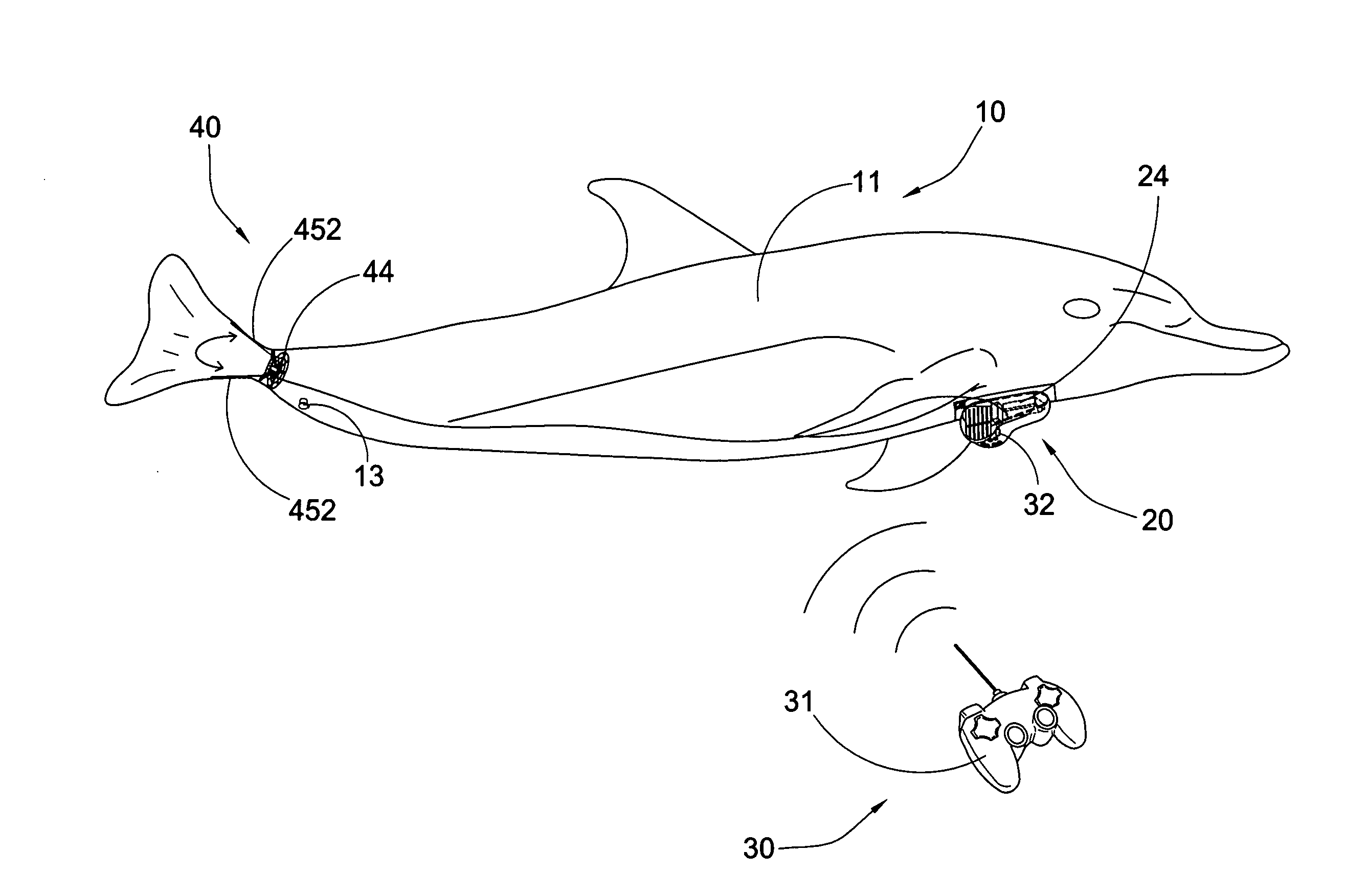
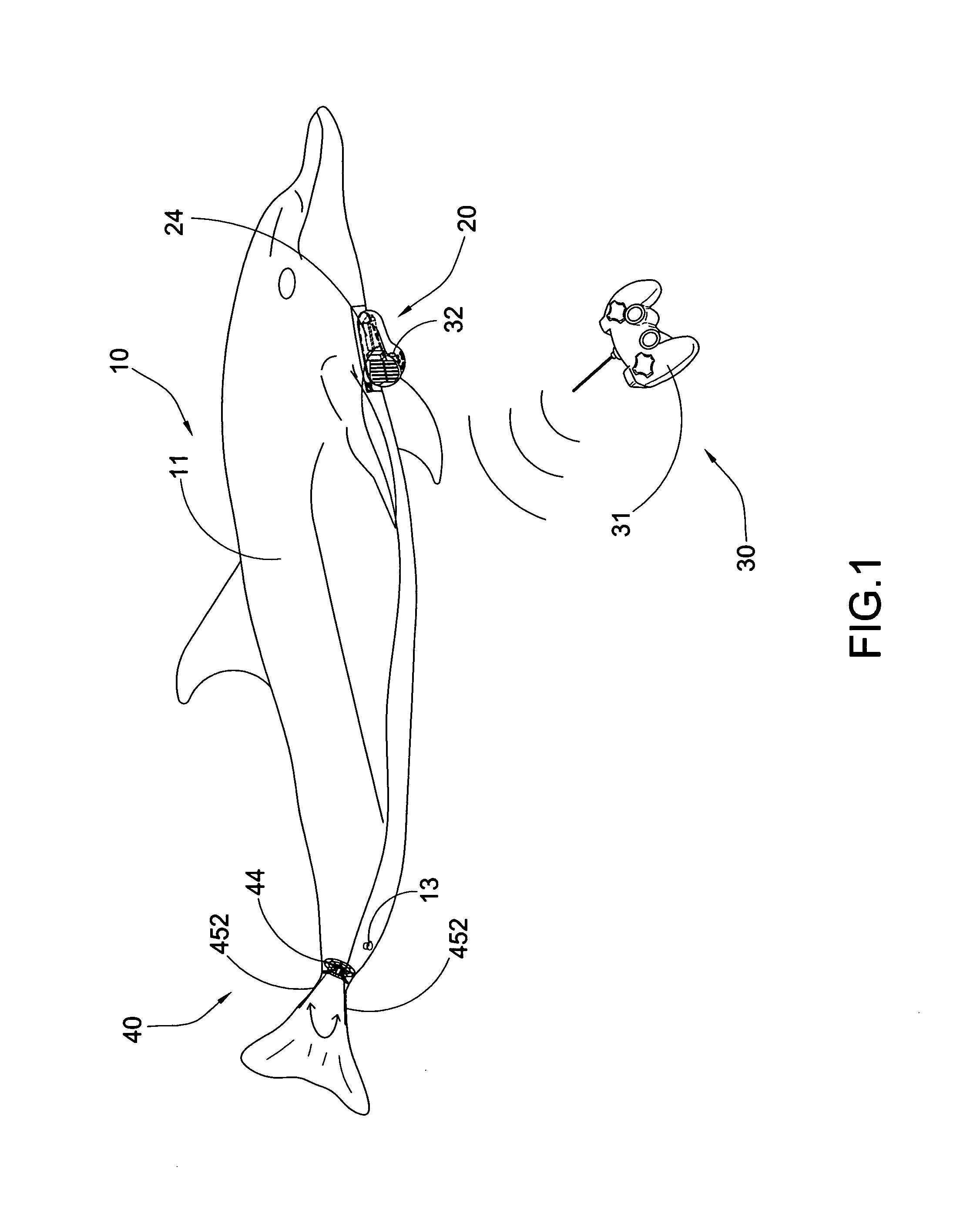
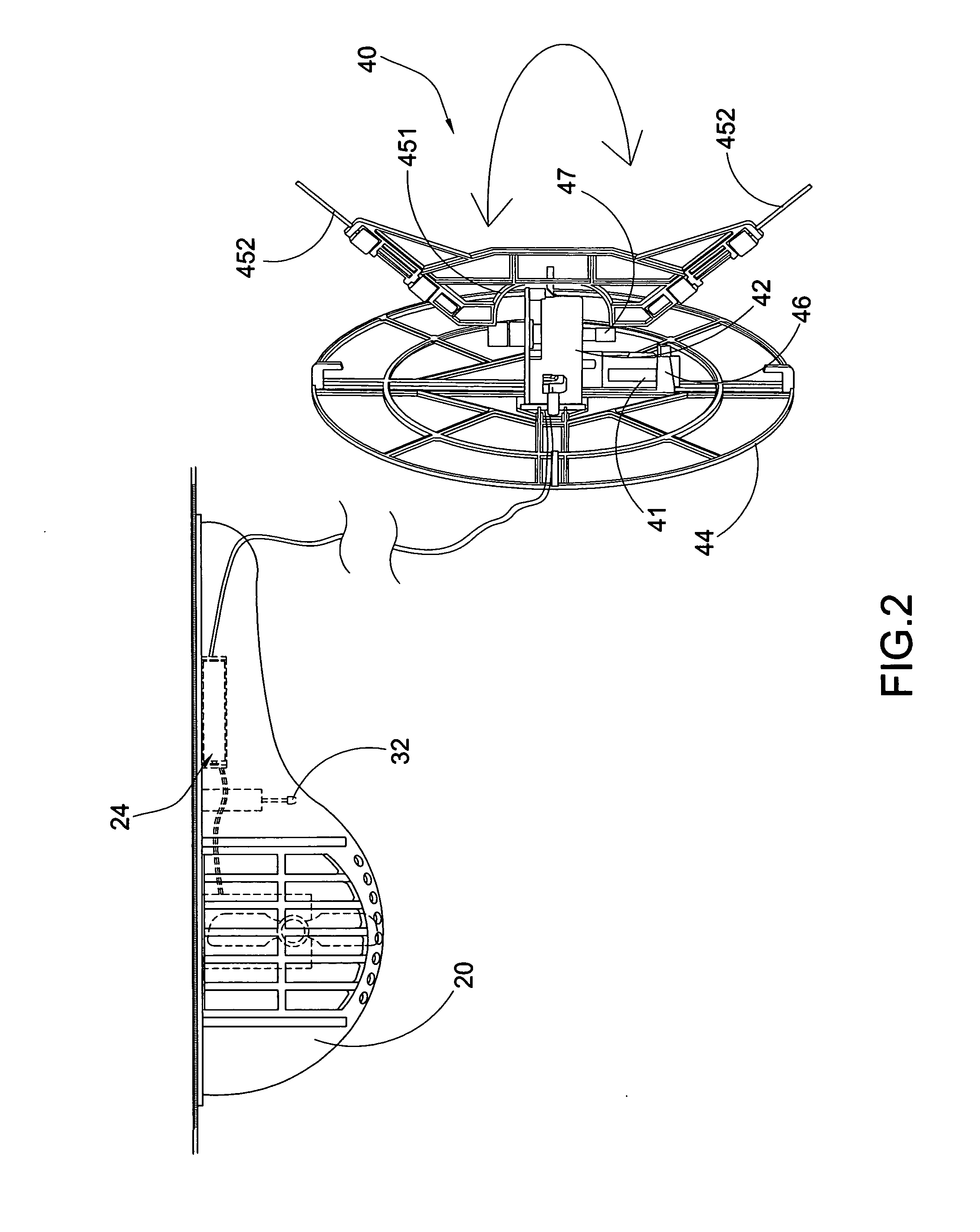
[0027]Referring to FIGS. 1 to 3 of the drawings, an air swimming toy according to a preferred embodiment of the present invention is illustrated, wherein the air swimming toy comprises a toy body 10, a driving device 20, a remote controller 30, and a steering device 40.
[0028]The toy body 10 comprises a floating body 11 and a tail body 12 movably coupled with the floating body 11, wherein the floating body 11 is filled with a particular gas, such as helium, in order to float in the air. In particular, the toy body 10 further comprises a valve 13 provided at the floating body 11 for filling the gas thereinto. The floating body 11 is made of high quality, durable nylon material that will stay inflated for a relatively long period of time, such as a week. The gas can be refilled to the floating body 11 via the valve 13 to inflate the floating body 11.
[0029]Accordingly, when the tail body 12 is moved in a wiggling motion, the toy body 10 will move forward slowly and smoothly as the swimming motion in the air. The tail body 12 is also formed as a steering member of the toy body 10 that when the tail body 12 is moved sidewardly, the toy body 10 will turn correspondingly.
[0030]The driving device 20 of the present invention is used for controlling an altitude of the toy body 10 but not the forward driving movement thereof. In other words, the driving device 20 of the present invention is arranged for controllably elevating the toy body 10 and for controllably dropping down the toy body 10. The driving device 20 is coupled at a bottom side of the floating body 11 to elevate or drop down the air swimming toy so as to control the up and down movement thereof.
[0031]The steering device 40 provided at a connection between the floating body 11 and the tail body 12 to drive the tail body 12 to move in a wiggling motion. In other words, the steering device 40 not only forms a movable joint to connect the tail body 12 to the floating body 11 but also forms a propelling unit to drive and steering the toy body 10 forward.
[0032]As shown in FIGS. 2 to 4, the steering device 40 comprises a motorized unit 41 for generating a reciprocating power transmitting to the tail body 12 so as to generate a wiggling motion thereof. Accordingly, the motorized unit 41 is a DC motor and is controlled to generate a reversible rotating power as the reciprocating power to drive the tail body 12 to swing in a reciprocating manner with respect to the floating body 11. The motorized unit 41 comprises an output shaft 411 being driven to rotate in a reciprocating manner.
[0033]As shown in FIG. 4, the steering device 40 further comprises a gear housing 42 supported at the floating body 11 and a gear unit 43 received in the gear housing 42, wherein the gear unit 42 is operatively coupled to the motorized unit 41 for directly transmitting the reciprocating power to the tail body 11. In particular, the gear unit 43 is coupled at the output shaft 411 of the motorized unit 41 for transmitting the reciprocating power therefrom.
[0034]According to the preferred embodiment, the gear unit 43 comprises a plurality of driving gears having different diameter sizes to transmit the reciprocating power from the motorized unit 41. As shown in FIG. 4, the driving gears are configured to convert the rotational speed of the output shaft 411 of the motorized unit 41 into a swinging motion and to control the wiggling angle of the tail body 12. In other words, when the output shaft 411 of the motorized unit 41 is rotated at a predetermined angle, the tail body 12 is precisely driven to wiggle at a predetermined wiggling angle with respect to the floating body 11. Therefore, the wiggling angle of the tail body 12, i.e. the angle of the tail body 12 being wiggled from one side to the other side, will be maximized. In addition, through the gear unit 43, the reciprocating power from the motorized unit 41 can be evenly and smoothly transmitted to the tail body 12 so as to smoothly wiggle the tail body 12 from one side to the other side. Furthermore, the toy body 10 can be steered via the direction of the tail body 12 via the motorized unit 41 that when the tail body 12 is driven to wiggle at one side via the rotational power of the motorized unit 41, the toy body 10 will turn at the corresponding direction.
[0035]The steering device 40 further comprises a base frame 44 affixed to the floating body 11 to support the motorized unit 41 thereat and a wiggling frame 45 coupled to the tail body 12, wherein the wiggling frame 45 is movably coupled with the base frame 44 via the gear unit 43. In particular, the wiggling frame 45 is operatively driven by the motorized unit 41 to drive the tail body 12 moving in a wiggling motion.
[0036]According to the preferred embodiment, the base frame 44 has a circular shape and is coupled at a rear portion of the floating body 11, wherein the gear housing 42 is coupled at the center of the base frame 44. The steering device 40 further comprises a motor housing 46 supported at the base frame 44 at a position adjacent to the gear housing 42, wherein the motorized unit 41 is received at the motor housing 46. The output shaft 411 of the motorized unit 41 is extended from the motor housing 46 to the gear housing 42 so as to operatively couple with the gear unit 42 therewithin.
[0037]The motor housing 46 is coupled at the base frame 44 at a position that the output shaft 411 of the motorized unit 41 is radially extended with respect to the base frame 44 in order to couple with the gear unit 42.
[0038]It is worth mentioning that the motorized unit 41 and the gear unit 43 are received at the motor housing 46 and the gear housing 42, which are supported at the base frame 44. In other words, the overall weight of the motorized unit 41, the gear housing 42, the gear unit 43, and the motor housing 46 are supported at the base frame 44 via the floating body 11. Therefore, the overall weight at the wiggling frame 45 will be minimized to enable the reciprocating power from the motorized unit 41 transmitting to the wiggling frame 45 effectively.
[0039]In order to couple the wiggling frame 45 to the gear unit 43, the steering device 40 further comprises a swing shaft 47 extended through the gear housing 42 to operatively couple with the gear unit 43, wherein the swing shaft 47 is driven to rotate reciprocatingly by the reciprocating power of the motorized unit 41 through the gear unit 43. In particular, the wiggling frame 45 is coupled at the swing shaft 47, such that when the swing shaft 47 is driven to rotate in a reciprocating manner, the wiggling frame 45 is moved in a wiggling motion.
[0040]According to the preferred embodiment, the wiggling frame 45 comprises a U-shaped retention member 451 and two elongated retention arms 452 inclinedly extended from the retention member 451 to form a V-shaped configuration. Accordingly, the retention member 451 has two coupling ends coupled at two end portions of the swing shaft 47 respectively, wherein the gear housing 42 is positioned between the two coupling ends of the retention member 451 to minimize the distance between the base frame 44 and the wiggling frame 45.
[0041]The tail body 12 is coupled at the wiggling frame 45 via the retention arms 452, wherein two side edges of the tail body 12 are detachably coupled with the retention arms 452, such as by clipping, respectively so as to securely couple the tail body 12 with the floating body 11 via the steering device 40.
[0042]As shown in FIG. 2, the driving device 20 further comprises a battery compartment 24 for replaceably receiving a battery thereat to electrically connect to the motorized unit 41 via a connection cable. The battery compartment 24 is provided at the bottom side of the toy body 10.
[0043]According to the preferred embodiment, the remote controller 30 is remotely controlling the driving device 20 and the steering device 40. In particular, the remote controller 30 is wirelessly control the driving device 20 and the steering device 40. Therefore, the remote controller 30 is arranged to control the altitude of the toy body 10 via the driving device 20, and is arranged to control the steering and propelling of the toy body 10 via the steering device 40.
[0044]As shown in FIGS. 1 and 2, the remote controller 30 comprises a handheld control 31 and a remote receiver 32 wirelessly connected to the handheld control 31, wherein the remote receiver 32 is housed in the driving device 20 and is operatively linked to the motorized unit 41 to control an operation of the motorized unit 41. Preferably, the handheld control 32 is wirelessly linked to the remote receiver 32 via radio frequency (RF) connection, Infrared (IF) connection or other wireless connections. Accordingly, the remote receiver 32 comprises a control circuit and a remote antenna electrically coupled thereto, wherein the motorized unit 41 is operatively coupled at the control circuit of the remote receiver 32. Therefore, when the remote receiver 32 receives a control signal from the handheld control 31, the motorized unit 41 is activated to control the operation of the motorized unit 41. In addition, the driving device 20 is also operatively linked to the control circuit of the remote receiver 32, such that when the remote receiver 32 receives a control signal from the handheld control 31, the driving device 20 is activated to control the altitude of air swimming toy.
[0045]It is worth mentioning that the rotational speed of the output shaft 411 of the motorized unit 41 can be controllably adjusted via the remote controller 30, wherein when the rotational speed of the output shaft 411 is increased, the tail body 12 will be correspondingly driven faster in a wiggling motion.
[0046]One skilled in the art will understand that the embodiment of the present invention as shown in the drawings and described above is exemplary only and not intended to be limiting.
[0047]It will thus be seen that the objects of the present invention have been fully and effectively accomplished. It embodiments have been shown and described for the purposes of illustrating the functional and structural principles of the present invention and is subject to change without departure from such principles. Therefore, this invention includes all modifications encompassed within the spirit and scope of the following claims.

PUM

no PUM

Description & Claims & Application Information

We can also present the details of the Description, Claims and Application information to help users get a comprehensive understanding of the technical details of the patent, such as background art, summary of invention, brief description of drawings, description of embodiments, and other original content. On the other hand, users can also determine the specific scope of protection of the technology through the list of claims; as well as understand the changes in the life cycle of the technology with the presentation of the patent timeline. Login to view more.

Similar technology patents

Polyaxial bone anchoring device

ActiveUS20130123861A1small sizewide application
Owner:BIEDERMANN TECH GMBH & CO KG

Handheld System for Radar Detection

InactiveUS20080169960A1high reliabilitysmall size
Owner:ROSENBURY ERWIN T

Stream encoder and stream decoder

InactiveUS20070297509A1small sizecost reduction
Owner:PANASONIC CORP

Rotary joint structure of underwater electric manipulator

InactiveCN101045301Acompact structuresmall size
Owner:SHENYANG INST OF AUTOMATION - CHINESE ACAD OF SCI

Gas liquefaction plant

ActiveUS20170160009A1prevent complexityminimize installation space
Owner:JGC CORP
Why Eureka
Try Eureka