Techniques, systems and machine readable programs for magnetic resonance

a technology of magnetic resonance imaging applied in the field of magnetic resonance imaging techniques, systems and machine readable programs, can solve the problem of limit as to the amount of rf energy a patient under examination can be exposed

Inactive Publication Date: 2013-09-26
MILLIKELVIN TECH
View PDF3 Cites 6 Cited by
  • Summary
  • Abstract
  • Description
  • Claims
  • Application Information

AI Technical Summary

Benefits of technology

[0007]To achieve these and other advantages and in accordance with the purpose of the disclosure, as embodied herein, in one embodiment, the disclosure provides a method of performing a magnetic resonance protocol. The method includes providing a magnetic resonance device including (i) a main magnet for providing a background magnetic field along a first direction, (ii) at least one radio-frequency coil, and (iii) at least one gradient coil that can be controlled to define at least one region of interest. The method further includes defining a region of interest, introducing a sample to be studied into the region of interest and inducing electromagnetic feedback between the nuclear magnetization of at least one set of nuclei within the sample and at least one nearby resonant coil to cause the vector direction of the nuclear magnetization of the at least one set of nuclei to rotate to a desired angle with respect to the first direction of the background magnetic field to generate at least one electromagnetic pulse of transverse magnetization MXY. The method further includes detecting the pulse of transverse magnetization with the at least one radio-frequency coil.
[0008]In some implementations, the method can further include processing information obtained from a plurality of pulses of transverse magnetization to produce at least one of (i) an image, (ii) dynamic flow data, (iii) perfusion data, (iii) spectroscopic identity of chemical species, (iv) physiological data, or (v) metabolic data. In some embodiments, the electromagnetic feedback can be induced at least in part by substantially eliminating the presence of a gradient magnetic field in the at least one region of interest. The region of interest can include, for example, at least one voxel, and the at least one gradient coil can be adapted and configured to apply a magnetic field gradient in at least one of three mutually orthogonal directions. The electromagnetic feedback can be induced at least in part by selectively tuning the resonant coil to a predetermined resonant frequency.

Problems solved by technology

However, there are limits as to the amount of rf energy a patient under examination can be exposed to, commonly referred to as specific absorption ratio or “SAR” limits.

Method used


Image

  • Techniques, systems and machine readable programs for magnetic resonance
  • Techniques, systems and machine readable programs for magnetic resonance
  • Techniques, systems and machine readable programs for magnetic resonance

Examples


example

MKT™ Controller

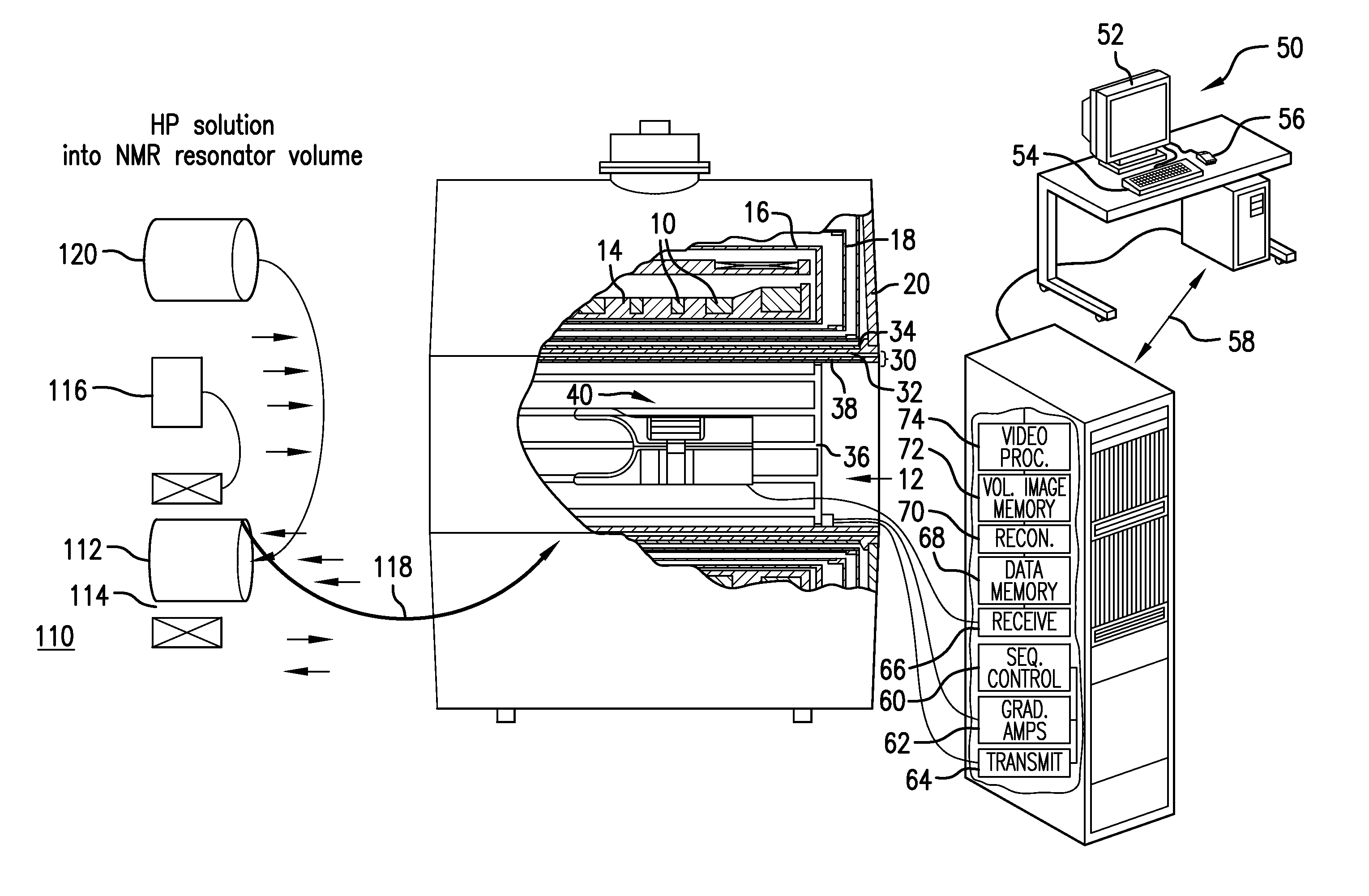
[0072]FIG. 5 illustrates inventive aspects of a MKT™ controller 601 for controlling a system such as that illustrated in FIG. 4 implementing some of the embodiments disclosed herein. In this embodiment, the MKT™ controller 601 may serve to aggregate, process, store, search, serve, identify, instruct, generate, match, and / or facilitate interactions with a computer through various technologies, and / or other related data.

[0073]Typically, a user or users, e.g., 633a, which may be people or groups of users and / or other systems, may engage information technology systems (e.g., computers) to facilitate operation of the system and information processing. In turn, computers employ processors to process information; such processors 603 may be referred to as central processing units (CPU). One form of processor is referred to as a microprocessor. CPUs use communicative circuits to pass binary encoded signals acting as instructions to enable various operations. These instructions...


PUM


Abstract

The present disclosure provides various methods and systems for performing magnetic resonance studies. In accordance with many embodiments, image or other information of interest is derived from super radiant pulses.

Description

CROSS-REFERENCE TO RELATED APPLICATIONS[0001]This application claims the benefit of priority of and is a continuation of International Patent Application No. PCT / US2012 / 30384, filed Mar. 23, 2012, which in turn claims the benefit of priority to U.S. Provisional Patent Application Ser. No. 61 / 466,500, filed Mar. 23, 2011 and U.S. Provisional Patent Application Ser. No. 61 / 522,076, filed Aug. 10, 2011. The disclosure of each of the aforementioned patent applications is incorporated by reference herein in its entirety.BACKGROUND OF THE DISCLOSURE[0002]1. Field of the Disclosure[0003]The present disclosure relates to improved techniques, systems and machine readable programs for magnetic resonance imaging.[0004]2. Description of Related Art[0005]Traditionally NMR / MRI / MRS studies have always incorporated pulses of radiofrequency (rf) radiation. The role of the rf pulses is to excite the system under investigation into a temporary state of non equilibrium magnetization. As the system rela...

Claims


Application Information

Patent Timeline
Patent Type & Authority Applications(United States)
IPC IPC(8): A61B5/055G01R33/44A61M5/00
CPCA61B5/055G01R33/5601G01R33/44A61M5/007
Inventor KALECHOFSKY, NEAL
Owner MILLIKELVIN TECH
Why Eureka
Try Eureka