Eureka AIR delivers breakthrough ideas for toughest innovation challenges, trusted by R&D personnel around the world.

System and method for controlling the pressure of hydraulic fluid supplied within a work vehicle transmission

Active Publication Date: 2013-09-26
BLUE LEAF I P
View PDF4 Cites 3 Cited by
  • Summary
  • Abstract
  • Description
  • Claims
  • Application Information

AI Technical Summary

Benefits of technology

The present invention relates to a method and system for controlling the pressure of hydraulic fluid supplied within a transmission of a work vehicle. The system includes an engine and a transmission with an input shaft, counter shaft, and at least two driven shafts extending parallel to the input and counter shafts. The transmission also has a plurality of clutches associated with the driven shafts and a valve for regulating the pressure of hydraulic fluid. The controller determines the desired pressure for the hydraulic fluid based on the load condition of the work vehicle and controls the valve accordingly. This invention allows for efficient and effective control of the hydraulic fluid pressure, resulting in improved performance and reliability of the work vehicle.

Problems solved by technology

Excessive parasitic power losses can generate multiple detrimental effects in vehicle operations, including lower effective working powers, decreased cooling efficiency, higher operating costs, increased noise and increased production of environmental pollutants.
Parasitic power losses for work vehicles, such as agricultural vehicles, earth-moving vehicles, off-road vehicles, loaders and / or the like, typically come from multiple sources.
For example, for work vehicles equipped with power shift transmissions and / or continuously variable transmissions, one major source for power losses derives from the hydraulic system used to control the transmission pressure.
However, more often than not, work vehicles are operated well below their maximum torque load.
Thus, by maintaining the pressure of the hydraulic fluid at such a high, fixed pressure value even when a work vehicle is operating at lower load conditions, conventional hydraulic systems generate excessive power losses.

Method used


Image

  • System and method for controlling the pressure of hydraulic fluid supplied within a work vehicle transmission
  • System and method for controlling the pressure of hydraulic fluid supplied within a work vehicle transmission
  • System and method for controlling the pressure of hydraulic fluid supplied within a work vehicle transmission

Examples


Embodiment Construction

[0015]Reference now will be made in detail to embodiments of the invention, one or more examples of which are illustrated in the drawings. Each example is provided by way of explanation of the invention, not limitation of the invention. In fact, it will be apparent to those skilled in the art that various modifications and variations can be made in the present invention without departing from the scope or spirit of the invention. For instance, features illustrated or described as part of one embodiment can be used with another embodiment to yield a still further embodiment. Thus, it is intended that the present invention covers such modifications and variations as come within the scope of the appended claims and their equivalents.

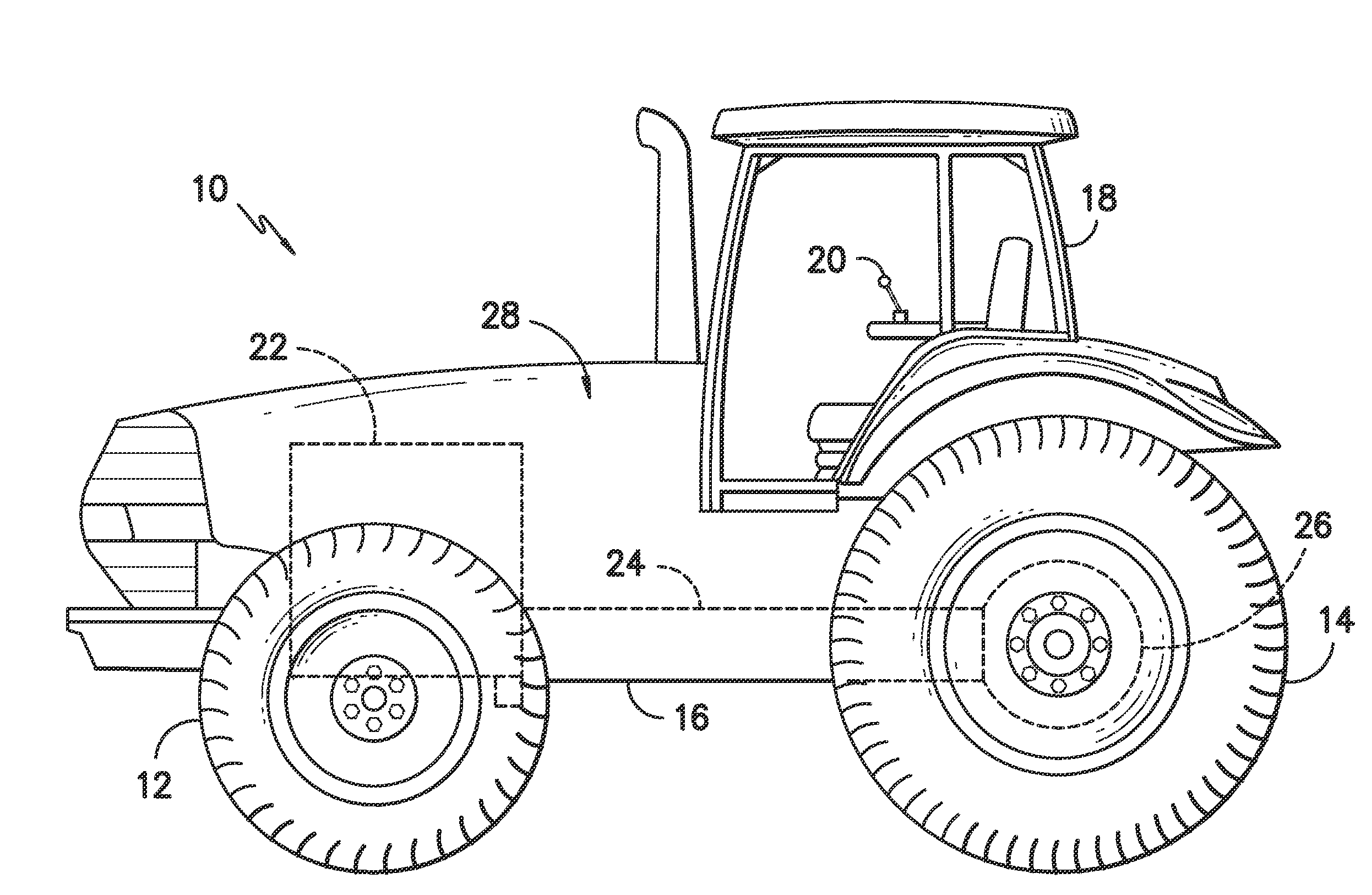
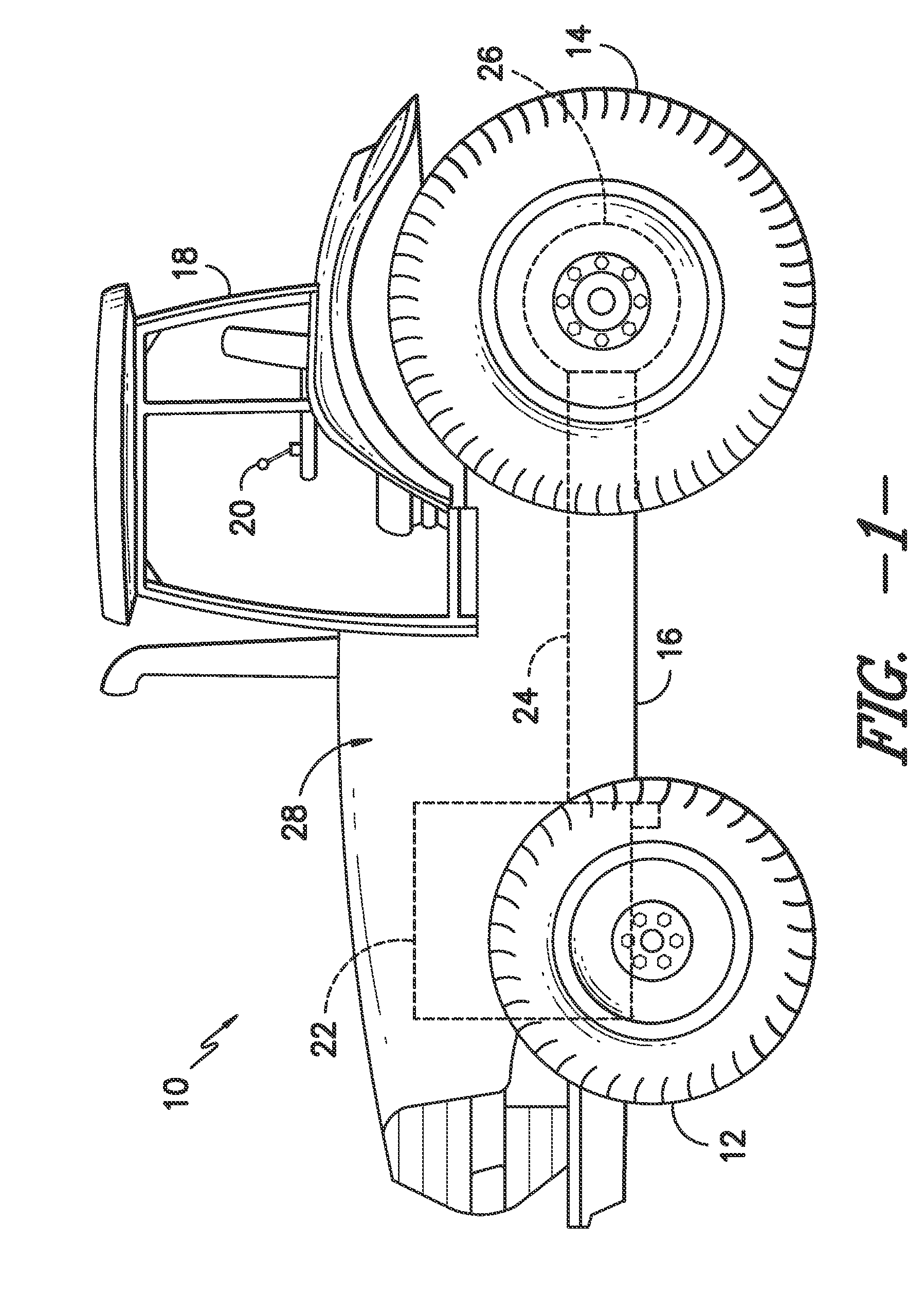
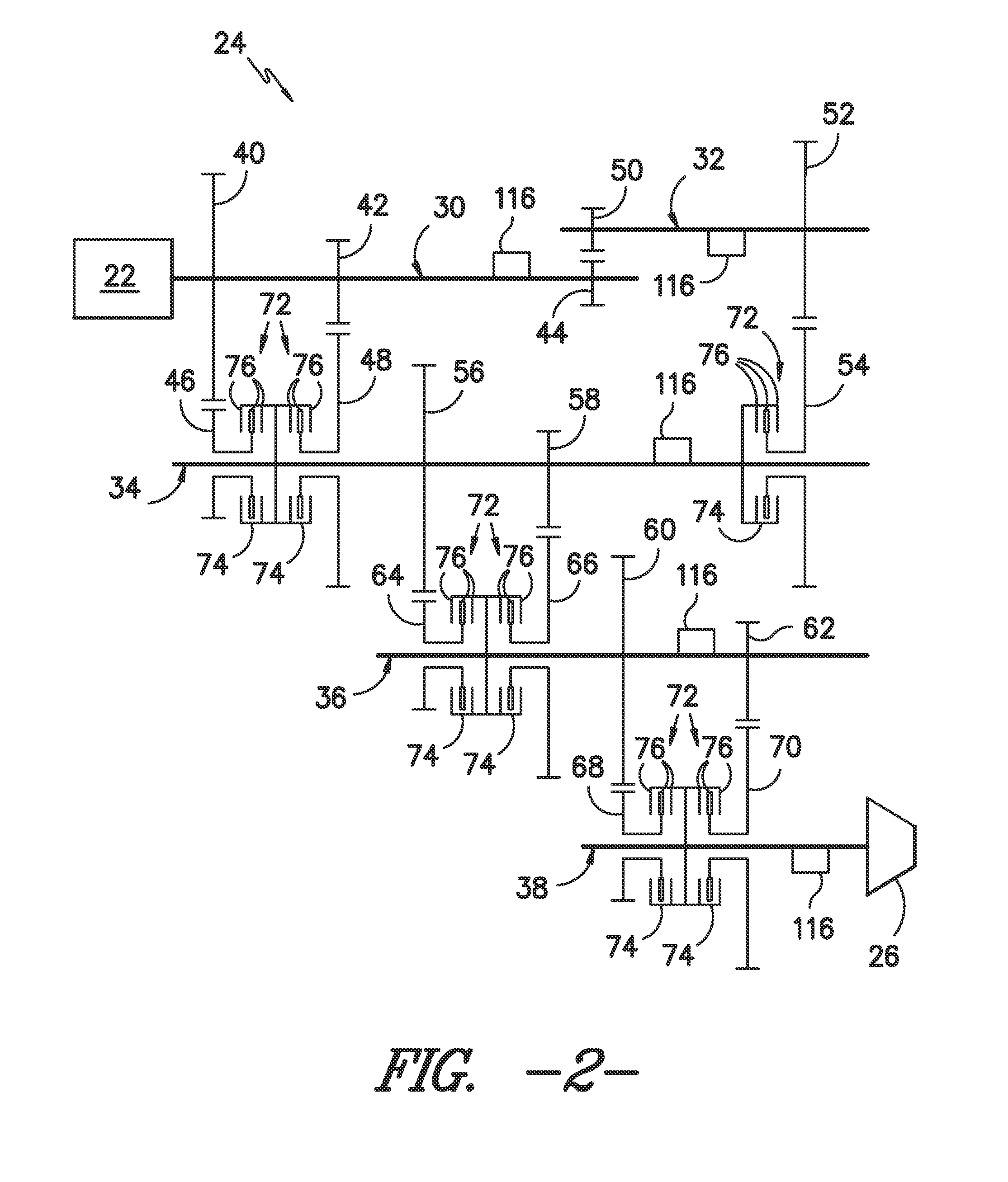
[0016]In general, the present subject matter is directed to a system and method for controlling the pressure of hydraulic fluid supplied within a transmission of a work vehicle. Specifically, in several embodiments, the system may include a controller confi...


PUM


Abstract

A method for controlling the pressure of hydraulic fluid supplied within a transmission of a work vehicle. The method may generally include receiving a signal associated with a load condition of the work vehicle, determining a desired pressure for the hydraulic fluid supplied within the transmission based on the load condition and controlling a valve such that hydraulic fluid is supplied within the transmission at the desired pressure, wherein the transmission includes an input shaft, a counter shaft and at least two driven shafts extending parallel to the input and counter shafts.

Description

CROSS-REFERENCE TO RELATED APPLICATIONS[0001]This application claims priority from and the benefit of U.S. Provisional Patent Application No. 61 / 615,488, entitled “System and Method For Controlling The Pressure Of Hydraulic Fluid Supplied Within A Work Vehicle Transmission,” filed Mar. 26, 2012, which is hereby incorporated by reference in its entirety.FIELD OF THE INVENTION[0002]The present subject matter relates generally to work vehicles and, more particularly, to a system and method for controlling the pressure of hydraulic fluid supplied within the transmission of a work vehicle.BACKGROUND OF THE INVENTION[0003]Higher vehicle efficiency has been vigorously pursued by design engineers for all vehicles. Excessive parasitic power losses can generate multiple detrimental effects in vehicle operations, including lower effective working powers, decreased cooling efficiency, higher operating costs, increased noise and increased production of environmental pollutants.[0004]Parasitic po...

Claims


Application Information

Patent Timeline
IPC IPC(8): F16H61/00
CPCF16H59/14F16H2059/465F16H61/0021F16D48/066F16D2500/111F16D2500/3024F16D2500/70406F16D2500/3065F16D2500/30814F16D2500/30822F16D2500/50296F16D2500/506F16D2500/30406
Inventor HOU, YANMING
Owner BLUE LEAF I P
Why Eureka
Eureka Blog
Learn More