
Determining a Magnetic Resonance System Control Sequence

a magnetic resonance system and control sequence technology, applied in the direction of reradiation, measurement using nmr, instruments, etc., can solve the problems of inability to apply linearization, inability to compensate for errors that are to be later arisen, radio-frequency load on the patient, etc., to achieve the target magnetization better, reduce the calculation time, the effect of reducing the local check-in tim

Inactive Publication Date: 2013-10-03
SIEMENS AG
View PDF6 Cites 0 Cited by
  • Summary
  • Abstract
  • Description
  • Claims
  • Application Information

AI Technical Summary

Benefits of technology

This patent provides a method for determining control sequences for magnetic resonance systems that reduces the risk of overloading patients with radio-frequency energy during the development of multichannel pulse trains. The method takes into account the local radio-frequency load and magnetization in a field of view using a computer program that can be loaded into a non-transitory computer readable storage medium. This approach allows for more efficient and accurate control sequences, even at large flip angles.

Problems solved by technology

Such an excitation leads to a radio-frequency load on the patient that is to be restricted in accordance with the usual rules, since too great a radio-frequency load may result in injuries to the patient.
The problem with this method of operation is that errors that are to be compensated for later arise as a result of the upscaling.
With a few newer pulses such as the “composite pulses,” for example, a linearization leads to completely incorrect results or is simply not able to be applied.

Method used


Image

  • Determining a Magnetic Resonance System Control Sequence
  • Determining a Magnetic Resonance System Control Sequence
  • Determining a Magnetic Resonance System Control Sequence

Examples


Embodiment Construction

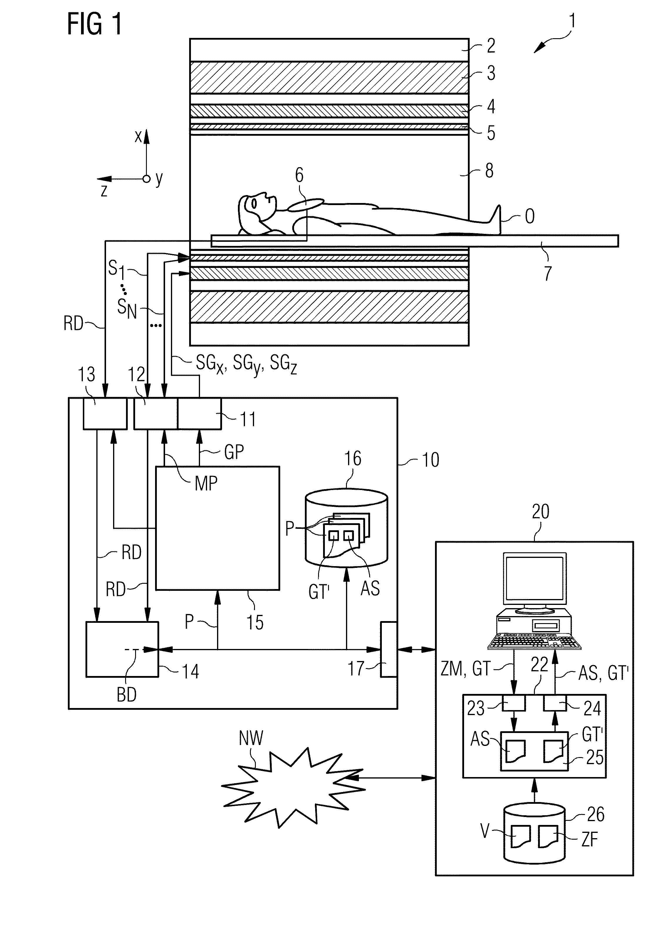
[0059]FIG. 1 shows an outline schematic diagram of one embodiment of a magnetic resonance system 1. The magnetic resonance system 1 includes an actual magnetic resonance scanner 2 with an examination space 8 or patient tunnel 8 located in the actual magnetic resonance scanner 2. A couch 7 is able to be moved into this patient tunnel 8 so that a patient O or sample lying on the couch 7 may be supported during an examination at a specific position within the magnetic resonance scanner 2 relative to the magnet system and radio-frequency system disposed therein or is also able to be moved during a measurement between different positions.

[0060]Components of the magnetic resonance scanner 2 are a basic field magnet 3, a gradient system 4 with magnet field gradient coils in order to apply magnetic field gradients in the x, y and z direction, and a radio-frequency whole body coil 5. Magnetic resonance signals induced in the object under examination O may be received via the whole body coil ...


PUM


Abstract

A method and a control sequence determination device are provided for determining a magnetic resonance control sequence that includes a multichannel pulse train with a number of individual RF pulse trains sent out in parallel by a magnetic resonance system over different independent radio-frequency transmit channels. The multichannel pulse train is calculated based on a predetermined target function with a predetermined target magnetization in an RF pulse optimization method. The RF pulse optimization method takes account of the magnetization in the form of a non-linear equation and of a local radio-frequency load and in a plurality of volume elements in the form of quadratic equation systems.

Description

[0001]This application claims the benefit of DE 10 2012 205 297.6, filed on Mar. 30, 2012, which is hereby incorporated by reference.BACKGROUND[0002]The present embodiments relate to a method and a control sequence determination device for determining a magnetic resonance system control sequence.[0003]In a magnetic resonance system, a body to be examined may be exposed with the aid of a basic field magnet system to a relatively high basic field magnetic field (e.g., of 3 or 7 Tesla). In addition, a magnetic field gradient is applied with the aid of a gradient system. Radio-frequency excitation signals (RF signals) are then transmitted by suitable antenna devices via a radio-frequency transmit system that is intended to lead to the nuclear spin of specific atoms resonantly excited by this radio frequency field being flipped locally-resolved by a defined flip angle in relation to the magnetic field lines of the basic magnetic field. This radio-frequency excitation or the resulting fli...

Claims


Application Information

Patent Timeline
Patent Type & Authority Applications(United States)
IPC IPC(8): G01R33/54
CPCG01R33/5612G01R33/543
Inventor FAUTZ, HANS-PETERGUMBRECHT, RENE
Owner SIEMENS AG
Learn More