Negative pressure earphone

a negative pressure, earphone technology, applied in the field of earphones, can solve the problems of difficult to achieve optimal sound performance, diaphragm deformation, unpleasant noise, etc., and achieve the effect of improving sound effect and rapid air flow

Active Publication Date: 2013-10-03
EASTERN TECH HLDG
View PDF1 Cites 52 Cited by
  • Summary
  • Abstract
  • Description
  • Claims
  • Application Information

AI Technical Summary

Benefits of technology

[0006]A negative pressure earphone is disclosed. The negative pressure earphone of the present invention comprises a main body, a cover portion, a silica gel earplug, a filtering net and a moving coil sound unit. The silica gel earplug is fitted to the protruding end of the main body. The filtering net is provided on the opening of the protruding end and the moving coil sound unit is disposed inside the main body. The cover portion is fitted to the other end of the main body. A sealing framework portion is disposed inside the main body and the moving coil sound unit is fitted to the sealing framework portion. A negative pressure portion is disposed on the sealing framework portion. The moving coil sound unit and the negative pressure portion are fitted to the sealing framework portion. The negative pressure earphone of the present invention is structurally simple and water resistant and does not have to have an opening in the cover portion and main body. An object of the present invention is to provide a negative pressure earphone in which the incoming air flow may be diverted to avoid the deformation of the diaphragm caused by the rapid air flow as the earphone is inserted into an ear.
[0013]With the presence of the negative pressure portion, the deformation of the diaphragm caused by the rapid air flow as the earphone is inserted into an ear may be avoided and better sound effect (especially the low-pitched sounds) may be achieved. Therefore, in the negative pressure earphone of the present invention, the openings in the main body and the cover portion in the prior art are not needed. Moreover, the concept of the present invention may be used in the underwater water resistant earphones, which do not have such negative pressure portion in the prior art.

Problems solved by technology

However, as the earphone is attached to an ear, a rapid air flow is generated and causes the diaphragm to deform and generate the unpleasant noises.
Moreover, with the presence of these openings 10 and 11, to achieve the optimal sound performance is relatively difficult.

Method used


Image

  • Negative pressure earphone
  • Negative pressure earphone
  • Negative pressure earphone

Examples


Embodiment Construction

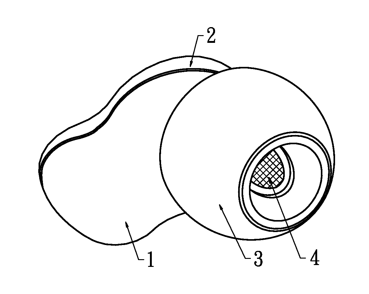
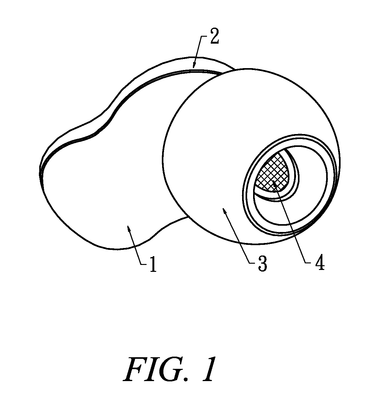
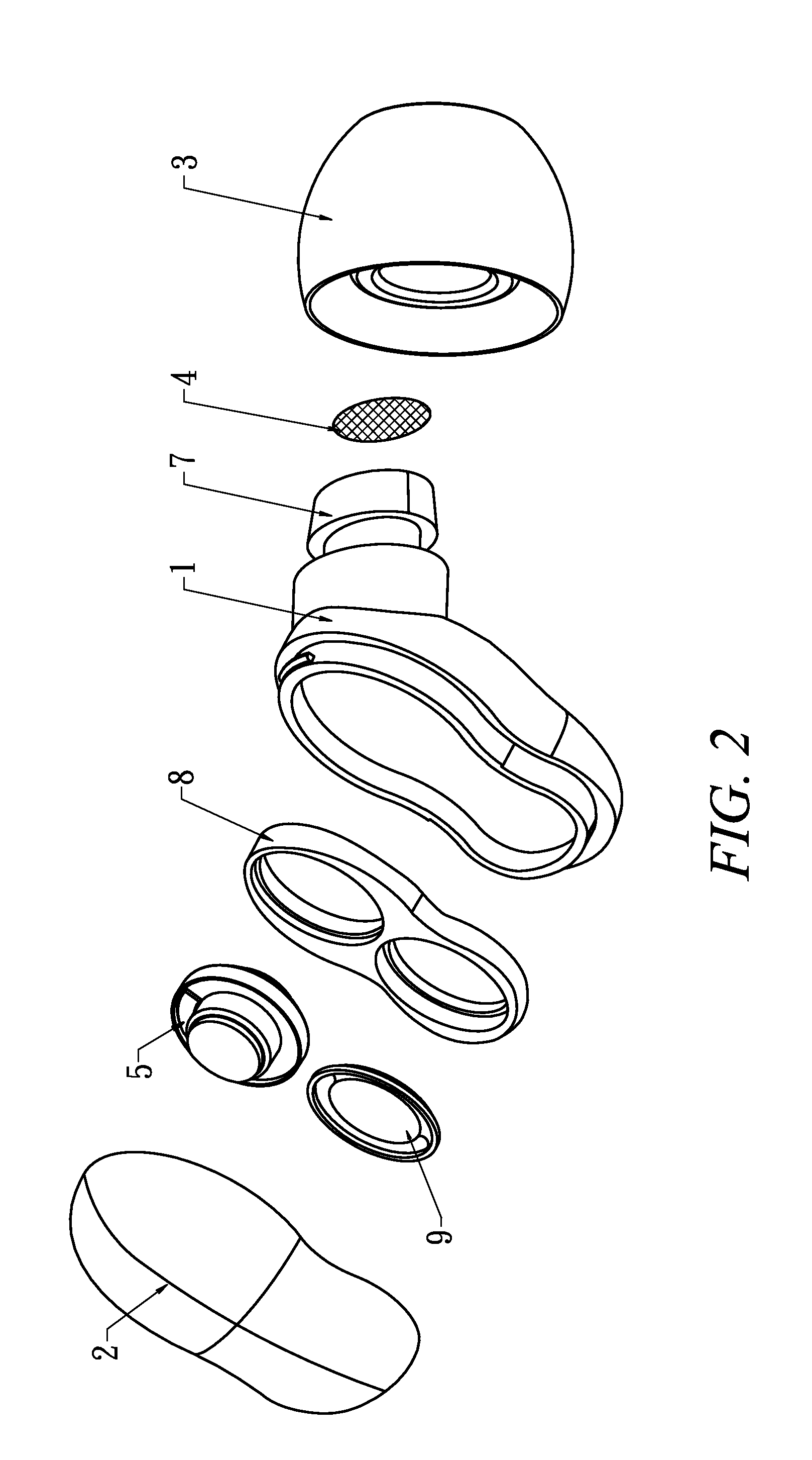
[0020]The features and advantages of the present invention will be fully understood and appreciated from the following detailed description of the accompanying drawings. The negative pressure earphone of the present invention is illustrated in FIGS. 1, 2 and 3. The negative pressure earphone of the present invention comprises a main body 1, a cover portion 2, a silica gel earplug 3, a filtering net 4 and a moving coil sound unit 5. A diaphragm 6 is provided on the moving coil sound unit 5 and the silica gel earplug 3 is fitted to the protruding end of the main body 1. The filtering net 4 is provided on the opening of the protruding end and the moving coil sound unit 5 is disposed inside the main body 1. The cover portion 2 is fitted to the other end of the main body 1. A sealing framework portion 8 is disposed inside the main body 1 and the moving coil sound unit 5 is fitted to the sealing framework portion 8. A negative pressure portion 9 is disposed on the sealing framework portio...


PUM


Abstract

A negative pressure earphone includes a main body, a cover portion, a silica gel earplug, a filtering net and a moving coil sound unit. The silica gel earplug is fitted to the protruding end of the main body. The filtering net is provided on the opening of the protruding end and the moving coil sound unit is disposed inside the main body. The cover portion is fitted to the other end of the main body. A sealing framework portion is disposed inside the main body and the moving coil sound unit is fitted to the sealing framework portion. A negative pressure portion is disposed on the sealing framework portion. The negative pressure earphone of the present invention is structurally simple and water resistant and does not have to have an opening in its cover portion.

Description

BACKGROUND OF THE INVENTION[0001]1. Field of the Invention[0002]The invention generally relates to an earphone. More particularly, the invention relates to a negative pressure earphone.[0003]2. Description of the Prior Art[0004]In the conventional earphones, a moving-coil sound-generating unit works according to the principles of electromagnetism and Fleming's left-hand rule. As electricity is fed to the sound generating unit, a diaphragm starts to vibrate. However, as the earphone is attached to an ear, a rapid air flow is generated and causes the diaphragm to deform and generate the unpleasant noises.[0005]Please refer to FIG. 5, which illustrates the conventional earphone. The earphone comprises a main body 1, a cover portion 2, a silica gel earplug 3, a filtering net 4 and a moving coil sound unit 5. The silica gel earplug 3 is fitted to the protruding end 111 of the main body 1. The filtering net 4 is provided on the opening of the protruding end and the moving coil sound unit ...

Claims


Application Information

Patent Timeline
Patent Type & Authority Applications(United States)
IPC IPC(8): H04R1/10
CPCH04R1/1016H04R1/44H04R1/2834
Inventor CHUNG, CHU MINGTANG, LEE PIN
Owner EASTERN TECH HLDG
Why Eureka
Try Eureka