Ship having an opening for removing a power supply system

a power supply system and power supply technology, applied in the field of ships, can solve the problems of only being able to carry out installation and removal operations, and being unable to carry out, and achieve the effects of reducing complication and expenditure, avoiding endangering the operation of the ship, and reducing the cost of operation

Active Publication Date: 2013-10-03
WOBBEN PROPERTIES GMBH
View PDF3 Cites 4 Cited by
  • Summary
  • Abstract
  • Description
  • Claims
  • Application Information

AI Technical Summary

Benefits of technology

[0021]Further preferably the control unit is adapted to make a selection in respect of switching on and shutting down individual diesel-electric systems in dependence on the respectively detected operating hours, in such a way that a difference, which is preferably respectively uniform, is maintained between the diesel-electric systems, in respect of the number of operating hours. It has proven to be particularly advantageous not to use the diesel-electric systems as uniformly as possible, but instead to maintain an intentional ‘inequality of distribution’ of the use of the diesel-electric systems, for the following reason: if all diesel-electric systems in the ship are uniformly loaded, they all reach a critical number of operating hours after a given, equal time and are all in need of maintenance at the same time. Consequently, all diesel-electric systems have to be maintained at times which are close to each other. Therefore, no energy supply is available for the maintenance period and the ship is out of operation. If in contrast however only one diesel-electric system has reached its maintenance date, but the others have not yet done so, then only that one diesel-electric system has to be replaced. Operation of the ship without that one diesel-electric system and only with the other diesel-electric systems is possible and also replacement of the diesel-

Problems solved by technology

Installation and removal operations are only limitedly possible on the ship which, in the interior, affords only extremely limited space for arranging functional eleme

Method used


Image

  • Ship having an opening for removing a power supply system
  • Ship having an opening for removing a power supply system
  • Ship having an opening for removing a power supply system

Examples


Embodiment Construction

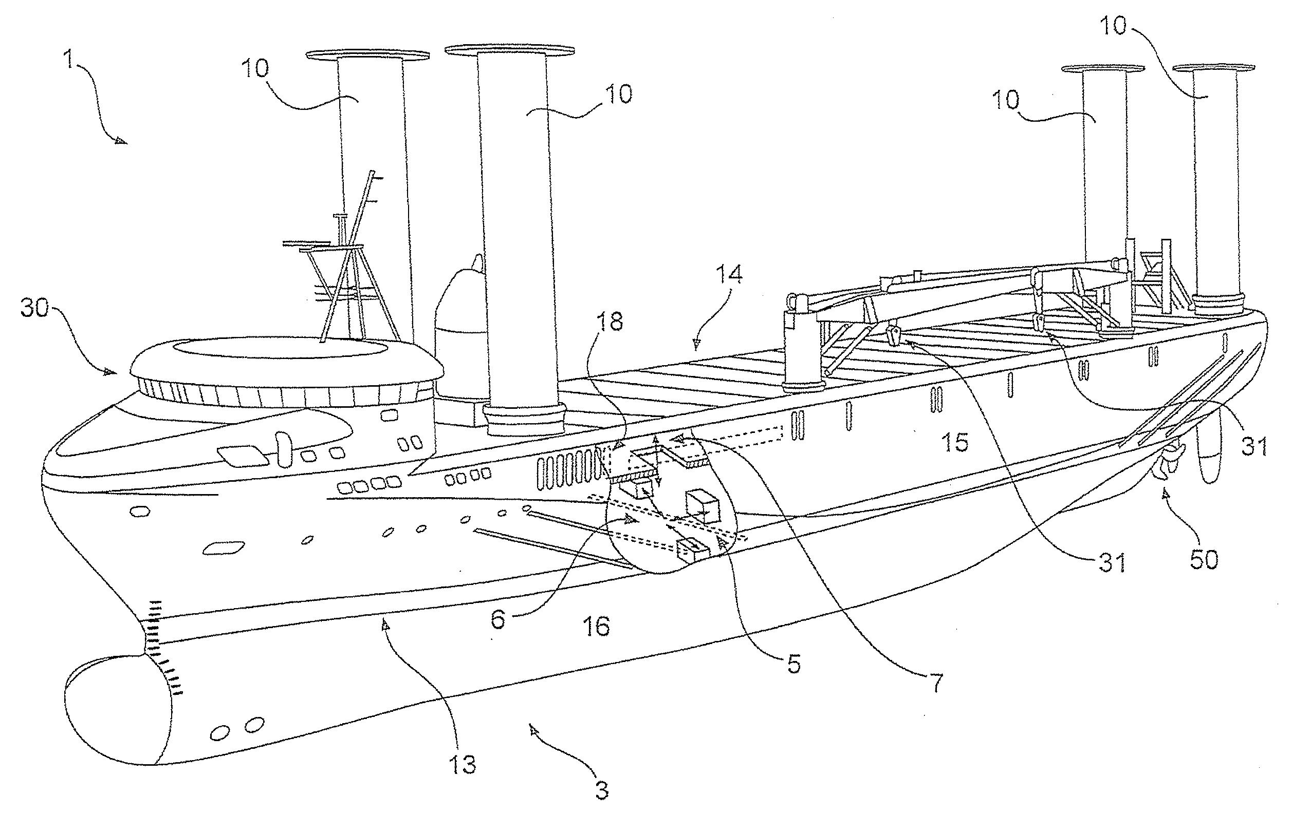
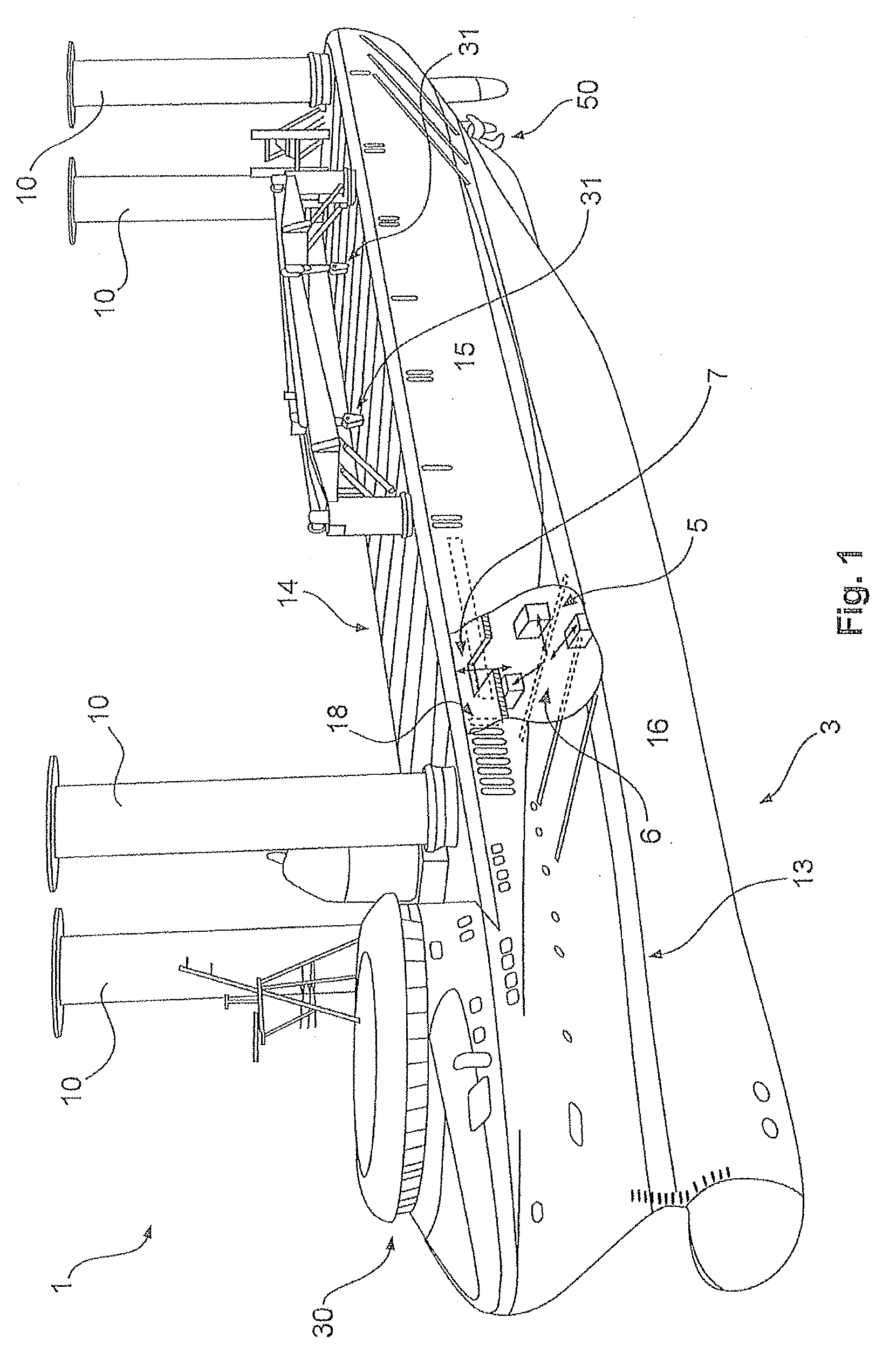
[0035]FIG. 1 shows a diagrammatic view of a ship 1 according to a first embodiment. In this case the ship 1 has a hull comprising an underwater region 16 and an above-water region 15. The ship 1 can further have for example four Magnus rotors or Flettner rotors 10 which can be arranged at the four corners of the hull. The ship 1 has a bridge 30 in the forecastle. The ship 1 has a propeller 50 underwater. For improved maneuverability the ship 1 can also have transverse thruster rudders, wherein preferably one is provided at the stern and one to two transverse thruster rudders are provided at the bow. Preferably those transverse thruster rudders are driven electrically. The bridge 30 and all superstructures above the weather deck 14 are of an aerodynamic configuration to reduce wind resistance. That is achieved in particular by sharp edges and sharp-edged structures being substantially avoided. As few superstructures as possible are provided to reduce wind resistances.

[0036]The ship 1...


PUM


Abstract

The invention relates to a ship, in particular a cargo ship, having a power supply system. The invention relates in particular to a ship having a plurality of diesel electric systems for providing electrical power that are disposed within the ship, wherein a plurality of diesel electric systems are each associated with a common opening for removing the diesel electric systems. The invention further relates to a power supply system for a ship and to a method for controlling the power supply system of a ship.

Description

BACKGROUND[0001]1. Technical Field[0002]The present invention concerns a ship, in particular a cargo ship, having an energy supply system. The invention further concerns an energy supply system for a ship, in particular a cargo ship. The invention further concerns a method of controlling an energy supply system of a ship.[0003]2. Description of the Related Art[0004]Ships of the aforementioned kind usually take electrical energy from an on-board energy supply system. In known ships the energy supply system has one or more diesel-electric systems which convert a mechanically produced power into electrical energy. The expression diesel-electric system is used to denote a system which is adapted to generate electrical energy and which has a (diesel) internal combustion engine for producing mechanical power, coupled to a generator for generating electrical energy.[0005]On ships of the kind set forth in the opening part of this specification the on-board network, communication devices, au...

Claims


Application Information

Patent Timeline
IPC IPC(8): B63B3/54B63H21/21B63H21/17B63H9/02
CPCB63H21/30B63J3/02B63H21/21B63H9/02B63H21/17B63B3/54G06Q10/20
Inventor ROHDEN, ROLF
Owner WOBBEN PROPERTIES GMBH
Why Eureka
Try Eureka