Adaptive power source control system

Inactive Publication Date: 2013-10-03
CATERPILLAR INC
View PDF0 Cites 5 Cited by
  • Summary
  • Abstract
  • Description
  • Claims
  • Application Information

AI Technical Summary

Benefits of technology

[0009]In an exemplary embodiment of the present disclosure, a method of controlling a power source associated with a machine includes determining a difference between an underspeed setpoint associated with a peak power source torque and a first power source speed. The method also includes determining a torque distribution associated with the power source and at least one parasitic load receiving power from the power source. The torque distribution is based on the difference and respective torque priority values associated with the power source and the at least one parasitic load. The method further includes providing torque from the power source to the at least one parasitic load based on the torque distribution and modifying at least one of the respective torque priority values. Modifying at least one of the torque priority values reduces a difference between the underspeed set point and a second power source speed different than the first power source speed.
[0010]In another exemplary embodiment of the present disclosure, a method of controlling a power source associated with a machine includes determining a cumulative torque demand based on signals received from an implement and a traction device, the implement and the traction device receiving power from the power source. The method also includes determining that the torque demand exceeds a peak power source torque and determining, in response to determining that the torque demand exceeds the peak power source torque, a first difference between a first power source speed and an underspeed setpoint. The method further includes determining a first torque distribution associated with the power source, the implement, and the traction device. The first torque distribution is based on t

Problems solved by technology

In addition, the at least one additional torque di

Method used


Image

  • Adaptive power source control system
  • Adaptive power source control system
  • Adaptive power source control system

Examples


Embodiment Construction

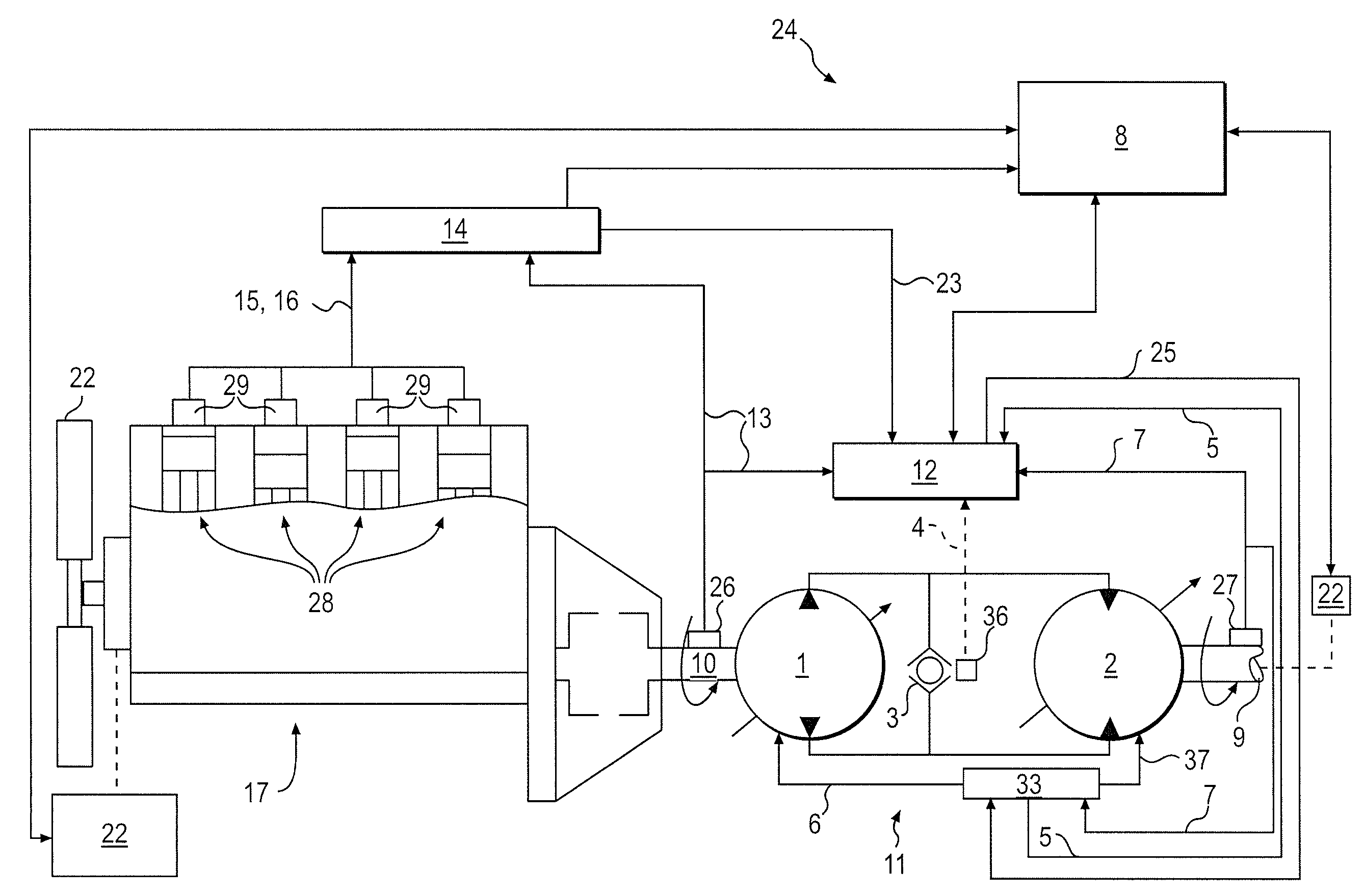
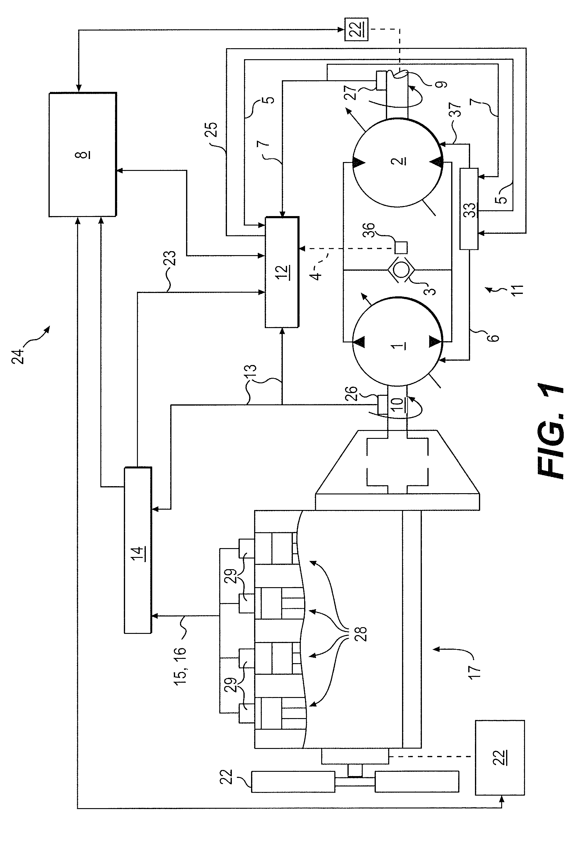
[0015]FIG. 1 illustrates an exemplary control system 24 of the present disclosure. The control system 24 may be used, for example, with a power source 17 and a transmission 11 associated with a machine (not shown). Such a machine may be, for example, any mobile or stationary machine used to perform work or other tasks. Such exemplary machines may include, but are not limited to, wheel loaders, motor graders, track-type tractors, excavators, power generators, on-highway vehicles, off-highway vehicles, and / or other like equipment. Such machines may be used to perform tasks in, for example, mining, excavating, construction, farming, transportation, and / or other like environments or applications.

[0016]In the exemplary embodiment of FIG. 1, the power source 17 is an engine, such as an internal combustion engine. The engine may be a diesel engine, a gasoline engine, a natural gas engine, or any other engine readily apparent to one skilled in the art. It is contemplated that the control sy...


PUM


Abstract

A method of controlling a power source associated with a machine includes determining a difference between an underspeed setpoint associated with a peak power source torque and a first power source speed. The method also includes determining a torque distribution associated with the power source and at least one parasitic load receiving power from the power source. The torque distribution is based on the difference and respective torque priority values associated with the power source and the at least one parasitic load. The method further includes providing torque from the power source to the at least one parasitic load based on the torque distribution and modifying at least one of the respective torque priority values. Modifying at least one of the torque priority values reduces a difference between the underspeed set point and a second power source speed different than the first power source speed.

Description

TECHNICAL FIELD[0001]This disclosure relates generally to a control system and, more particularly, to a system and method of controlling a power source.BACKGROUND[0002]Machines such as, for example, wheel loaders, track type tractors, and other types of heavy machinery can be used for a variety of tasks. These machines include a power source, which may be, for example, an engine, such as a diesel engine, gasoline engine, or natural gas engine that provides the power required to complete such tasks. To effectively maneuver the machine during performance of such tasks, the machines also include a transmission that is capable of transmitting the power generated by the engine to various drivetrain components over a wide range of conditions.[0003]For example, such machines commonly use a continuously variable transmission (“CVT”) to direct engine torque to traction devices, such as wheels or tracks, that propel the machine. A CVT is capable of providing a desired output torque to such co...

Claims


Application Information

Patent Timeline
IPC IPC(8): B60W10/06B60W10/10
CPCB60W10/06B60W10/103B60W10/30Y10T477/675B60W30/1886B60Y2200/415B60W30/18109
Inventor LI, WEI
Owner CATERPILLAR INC
Why Eureka
Try Eureka