Flexible drill bit

a flexible drill bit technology, applied in the field of surgical methods and equipment, can solve the problems of pathology pathology, pathology and approach to the interior of the hip joint, pathology and pathology of surgeons, etc., and achieve the effect of sufficient longitudinal flexibility and sufficient torsional strength

Active Publication Date: 2013-10-03
STRYKER PUERTO RICO LLC
View PDF5 Cites 16 Cited by
  • Summary
  • Abstract
  • Description
  • Claims
  • Application Information

AI Technical Summary

Benefits of technology

[0020]an intermediate shaft portion extending between the proximal shaft portion and the distal cutting tip portion, the intermediate shaft portion being characterized by (i) sufficient longitudinal flexibility so as to permit the flexible drill bit to be passed along a curve, and (ii) sufficient torsional strength to permit the flexible drill bit to bore into the material.

Problems solved by technology

Unfortunately, minimally-invasive treatments for pathologies of the hip joint have lagged far behind minimally-invasive treatments for pathologies of the shoulder joint and the knee joint.
As a result, it is generally relatively difficult for surgeons to perform minimally-invasive procedures on the hip joint.
Furthermore, the pathways and approaches for entering the interior of the hip joint (i.e., the natural pathways which exist between adjacent bones and / or delicate neurovascular structures) are generally much more limited for the hip joint than for the shoulder joint or the knee joint.
This limited access further complicates a surgeon's ability to effectively perform minimally-invasive procedures on the hip joint.
In addition to the foregoing, the nature and location of the pathologies of the hip joint also complicate a surgeon's ability to perform minimally-invasive procedures on the hip joint.
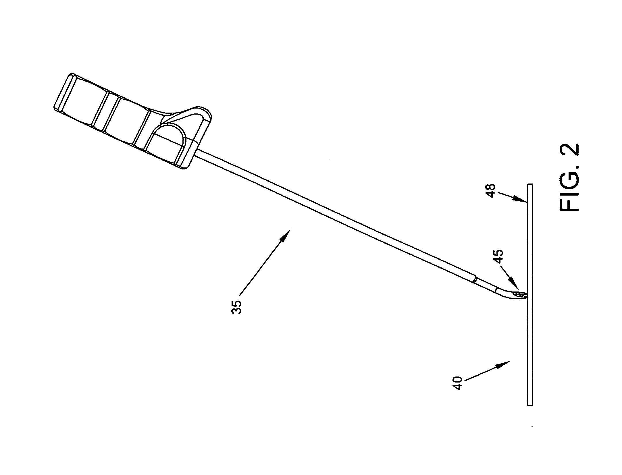
This makes drilling into bone, for example, a significantly more complicated procedure than in a case where the angle of approach is effectively aligned with the angle at which the instrument addresses the joint anatomy, such as is frequently the case in the shoulder joint.
Furthermore, since the working space within the hip joint is typically extremely limited, it is even more difficult to properly adjust the alignment of surgical instruments (e.g., a drill) where the angle of approach is not aligned with the optimal angle for the instrument to address the joint anatomy.
As a result of the foregoing, minimally-invasive hip joint procedures are still relatively difficult to perform and hence less common in practice.
Consequently, patients are typically forced to manage and endure their hip pain for as long as possible, until a resurfacing procedure or a partial or total hip replacement procedure can no longer be avoided.

Method used


Image

  • Flexible drill bit
  • Flexible drill bit
  • Flexible drill bit

Examples


Embodiment Construction

Flexible Drill Bit having a “Unibody” Construction

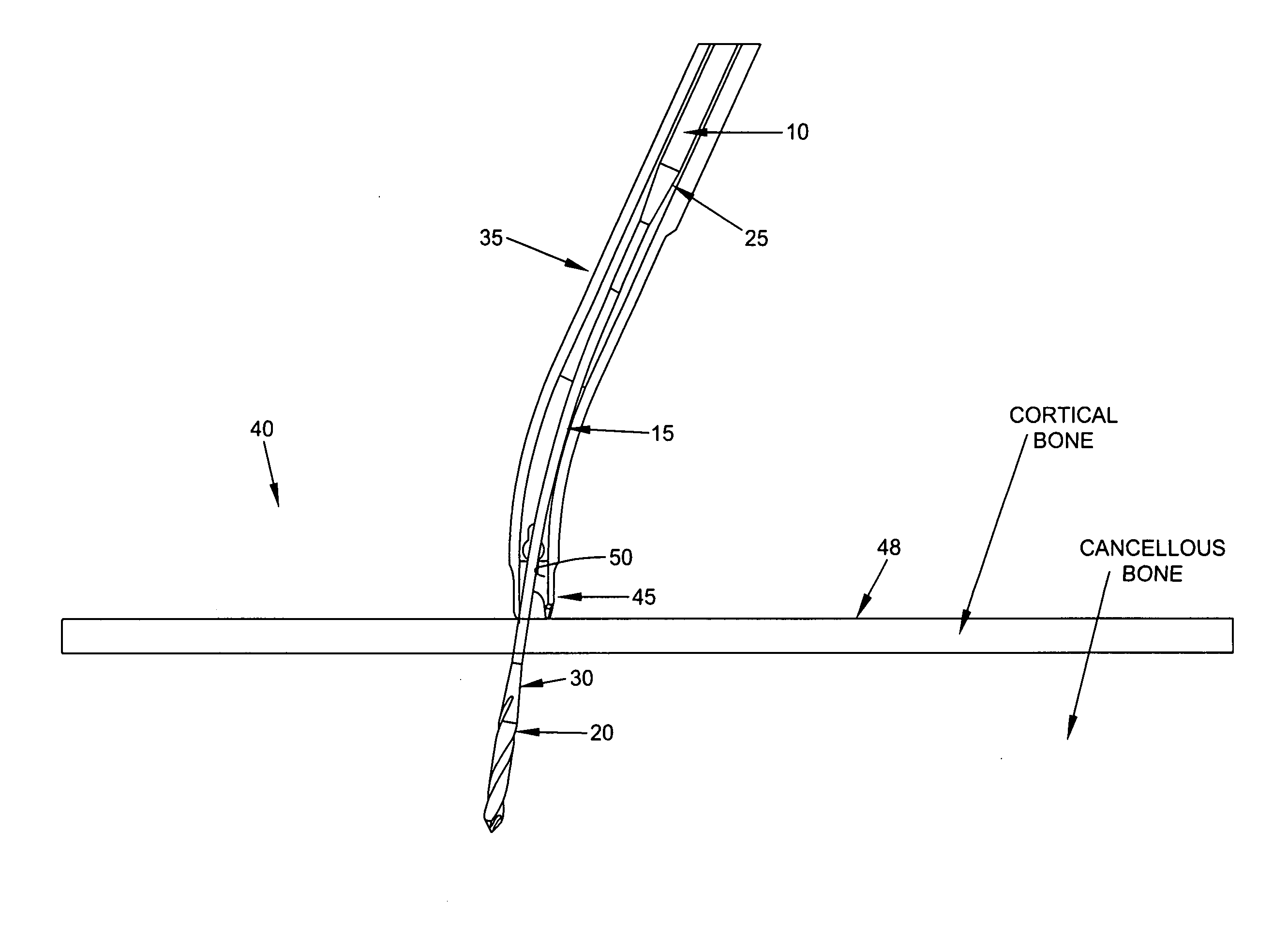
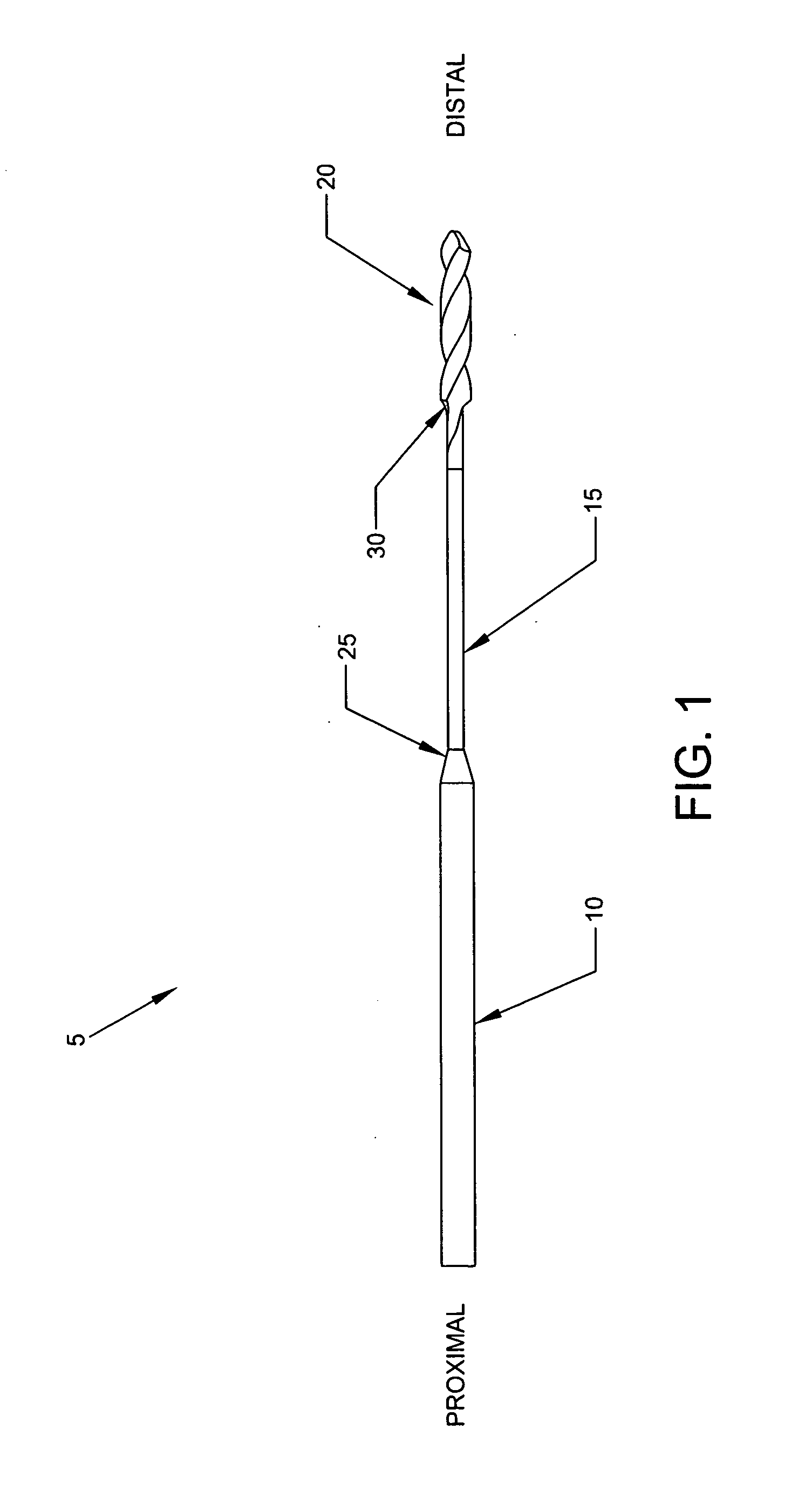
[0048]Looking first at FIG. 1, there is a shown a flexible drill bit 5 formed in accordance with the present invention. Flexible drill bit 5 comprises three sections, i.e., a full diameter shaft portion 10, a reduced diameter shaft portion 15, and a fluted cutting tip portion 20. Full diameter shaft portion 10, reduced diameter shaft portion 15, and fluted cutting tip portion 20 are all formed integral with one another so as to create a flexible drill bit having a “unibody” construction. If desired, a transition area 25 may be formed between full diameter shaft portion 10 and reduced diameter shaft portion 15, and / or a transition area 30 may be formed between reduced diameter shaft portion 15 and fluted cutting tip portion 20.

[0049]The “unibody” construction eliminates the need for a mechanical joint connecting the cutting tip of the flexible drill bit (e.g., fluted cutting tip portion 20) to the flexible portion of the flexible dril...


PUM


Abstract

A flexible drill bit comprising:
    • a proximal shaft portion for connecting to a source of turning;
    • a distal cutting tip portion for boring into a material; and
    • an intermediate shaft portion extending between the proximal shaft portion and the distal cutting tip portion, the intermediate shaft portion being characterized by (i) sufficient longitudinal flexibility so as to permit the flexible drill bit to be passed along a curve, and (ii) sufficient torsional strength to permit the flexible drill bit to bore into the material.

Description

REFERENCE TO PENDING PRIOR PATENT APPLICATION[0001]This patent application claims benefit of pending prior U.S. Provisional Patent Application Ser. No. 61 / 583,265, filed Jan. 5, 2012 by J. Brook Burley et al. for FLEXIBLE DRILL BIT (Attorney's Docket No. FIAN-73 PROV), which patent application is hereby incorporated herein by reference.FIELD OF THE INVENTION[0002]This invention relates to surgical methods and apparatus in general, and more particularly to methods and apparatus for drilling a hole in bone.BACKGROUND OF THE INVENTIONThe General Trend Toward Treating Joint Pathologies Using Minimally-Invasive, and Earlier, Interventions[0003]The current trend in orthopedic surgery is to treat joint pathologies using minimally-invasive techniques. Such minimally-invasive, “keyhole” surgeries generally offer numerous advantages over traditional, “open” surgeries, including reduced trauma to tissue, less pain for the patient, faster recuperation times, etc.[0004]By way of example but not ...

Claims


Application Information

Patent Timeline
Patent Type & Authority Applications(United States)
IPC IPC(8): A61B17/16
CPCA61B17/1615A61B17/17A61B17/1631
Inventor BURLEY, J. BROOKGRAUL, JEREMYPANDYA, SUDIPFLOM, JAMESLANTZ, ANDREW
Owner STRYKER PUERTO RICO LLC
Why Eureka
Try Eureka