Vehicle drive device

a technology of drive device and drive shaft, which is applied in the direction of electric devices, vehicle sub-unit features, automatic control systems, etc., can solve the problem that nothing is described about how to control the electric power of electric power sources, and achieve the effect of the rotation speed of the third rotation elemen

Active Publication Date: 2013-10-03
HONDA MOTOR CO LTD
View PDF1 Cites 28 Cited by
  • Summary
  • Abstract
  • Description
  • Claims
  • Application Information

AI Technical Summary

Benefits of technology

[0053]According to the second aspect of the present invention, although the left-right difference changes in some cases even if the left-right electric power sum is constant, control is performed so that the left-right difference becomes constant, whereby the change in a yaw moment due to the left-right difference can be suppressed.
[0054]According to the third aspect of the present invention, although the balance between the lef

Problems solved by technology

In the vehicle drive device described in Japanese Patent No. 3138799, however, nothing is described about how to control the electric power o

Method used


Image

  • Vehicle drive device
  • Vehicle drive device
  • Vehicle drive device

Examples


Embodiment Construction

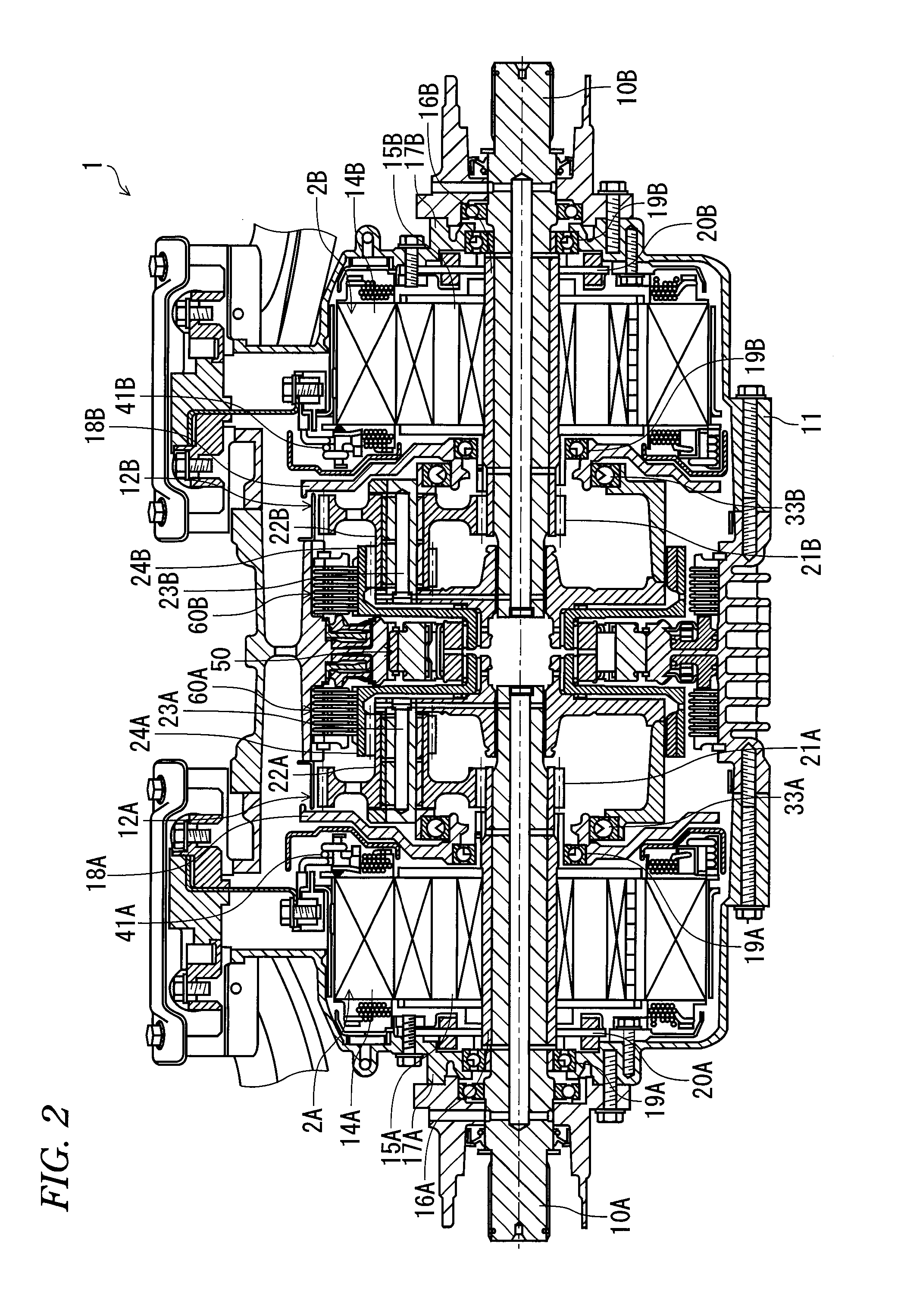
[0076]First, an embodiment of a vehicle drive device according to the present invention will be described based on FIGS. 1 to 3.

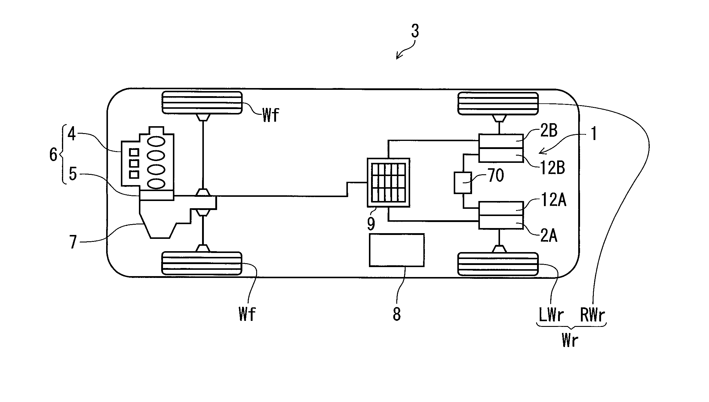
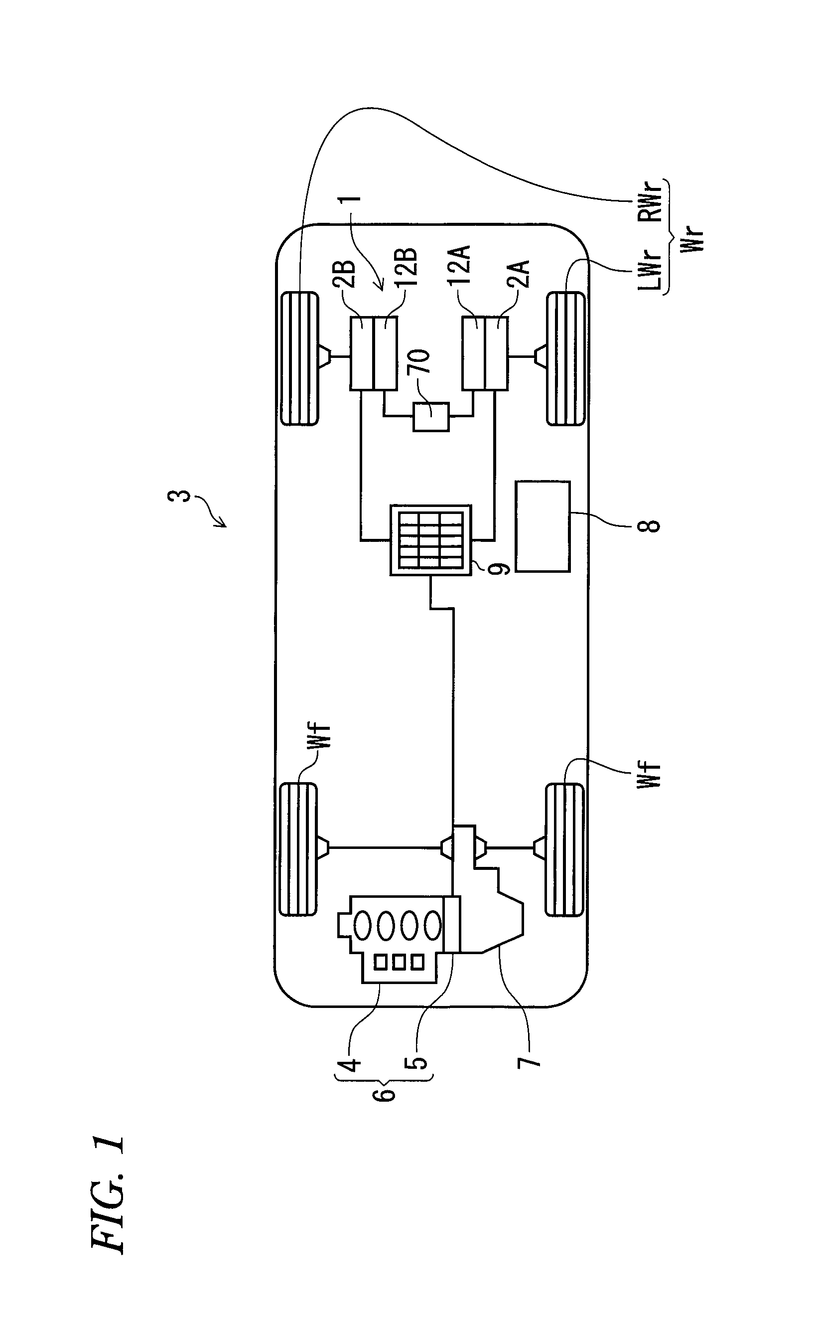
[0077]The vehicle drive device according to the present invention, in which electric motors serve as drive sources for driving axles, is used for a vehicle having such a drive system shown in FIG. 1, for example. In the following descriptions, a case in which the vehicle drive device is used to drive rear wheels is taken as an example. However, the vehicle drive device may also be used to drive front wheels.

[0078]The vehicle 3 shown in FIG. 1 is a hybrid vehicle having a drive unit 6 (hereafter referred to as a front wheel drive unit) including an internal combustion engine 4 and an electric motor 5 connected in series at the front section of the vehicle, and the drive power of this front wheel drive unit 6 is transmitted to front wheels Wf via a transmission 7; on the other hand, the drive power of a drive unit 1 (hereafter referred to as a rear wheel driv...


PUM


Abstract

An electric motor-generator controller (8) is configured to control a left electric power of the left electric motor-generator (2A) and a right electric power of the right electric motor-generator (2B), based on the sum of the left electric power and the right electric power, wherein the left electric power is defined as an electric power generated or consumed by the left electric motor-generator (2A) and, the right electric power is defined as an electric power generated or consumed by the right electric motor-generator (2B). The electric motor-generator controller (8) control the left electric power of the left electric motor-generator and the right electric power of the right electric motor-generator such that the sum of the left electric power and the right electric power becomes a constant value, when the rotation restrictor controller (8) controls the rotation restrictor (60A, 60B) such that the rotation restrictor releases the third rotation elements.

Description

CROSS-REFERENCE TO RELATED APPLICATION[0001]This application claims priority from Japanese Patent Applications No. 2012-082939, filed on Mar. 30, 2012, the entire contents of which are herein incorporated by reference.BACKGROUND[0002]1. Technical Field[0003]The present invention relates to a vehicle drive device provided with a left wheel drive unit for driving a left wheel and a right wheel drive unit for driving a right wheel.[0004]2. Description of the Related Art[0005]In Japanese Patent No. 3138799, a vehicle drive device is described which is equipped with a left wheel drive unit having a first electric motor for driving a left wheel of a vehicle and a first planetary gear transmission provided on the power transmission path between the first electric motor and the left wheel, and also equipped with a right wheel drive unit having a second electric motor for driving a right wheel of the vehicle and a second planetary gear transmission provided on the power transmission path bet...

Claims


Application Information

Patent Timeline
IPC IPC(8): B60W20/00B60W10/10B60W10/08B60L50/16
CPCB60K1/02Y02T10/7258B60K7/0007B60K17/046B60W30/18145B60K2006/381B60K2007/0092B60W2710/086B60W2720/14B60W20/00B60W10/08B60W10/10B60W2600/00Y10S903/93Y02T10/6265B60K17/356B60K6/52B60L1/003B60L3/0061B60L3/106B60L7/26B60L15/20B60L15/2009B60L15/2036B60L2240/12B60L2240/24B60L2240/421B60L2240/423B60L2240/441B60L2240/443B60L2240/445B60L2240/461B60L2240/463B60L2240/465B60L2240/662B60L2250/24B60L2250/26B60L2260/26Y02T90/16Y02T10/72B60L50/61B60L50/16B60L58/12B60K2007/0046B60Y2400/427Y02T10/62Y02T10/64Y02T10/70Y02T10/7072B60W2556/00
Inventor NOGUCHI, MASATOSHI
Owner HONDA MOTOR CO LTD
Why Eureka
Try Eureka