Vinyl Siding Sealer System

a technology of vinyl siding and sealer, which is applied in the direction of covering/lining, construction, building components, etc., can solve the problems that specific barriers have not worked

Inactive Publication Date: 2013-10-10
LEDGERWOOD GARY L
View PDF11 Cites 3 Cited by
  • Summary
  • Abstract
  • Description
  • Claims
  • Application Information

AI Technical Summary

Benefits of technology

[0009]It is an object of the present invention, therefore, to provide a vinyl siding sealer system solution t

Problems solved by technology

However, references exist in the litigation field that sp

Method used


Image

  • Vinyl Siding Sealer System
  • Vinyl Siding Sealer System
  • Vinyl Siding Sealer System

Examples


Embodiment Construction

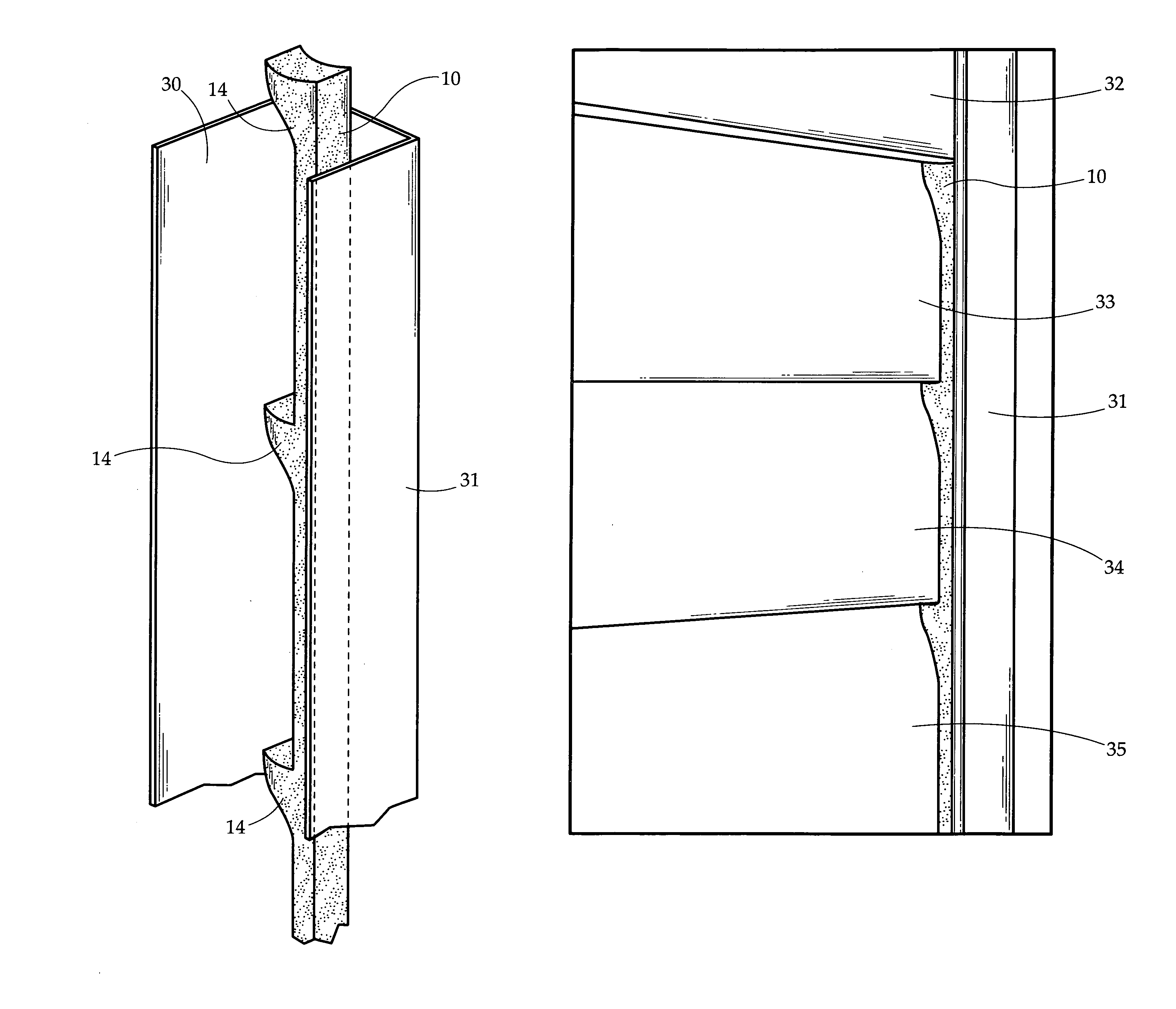
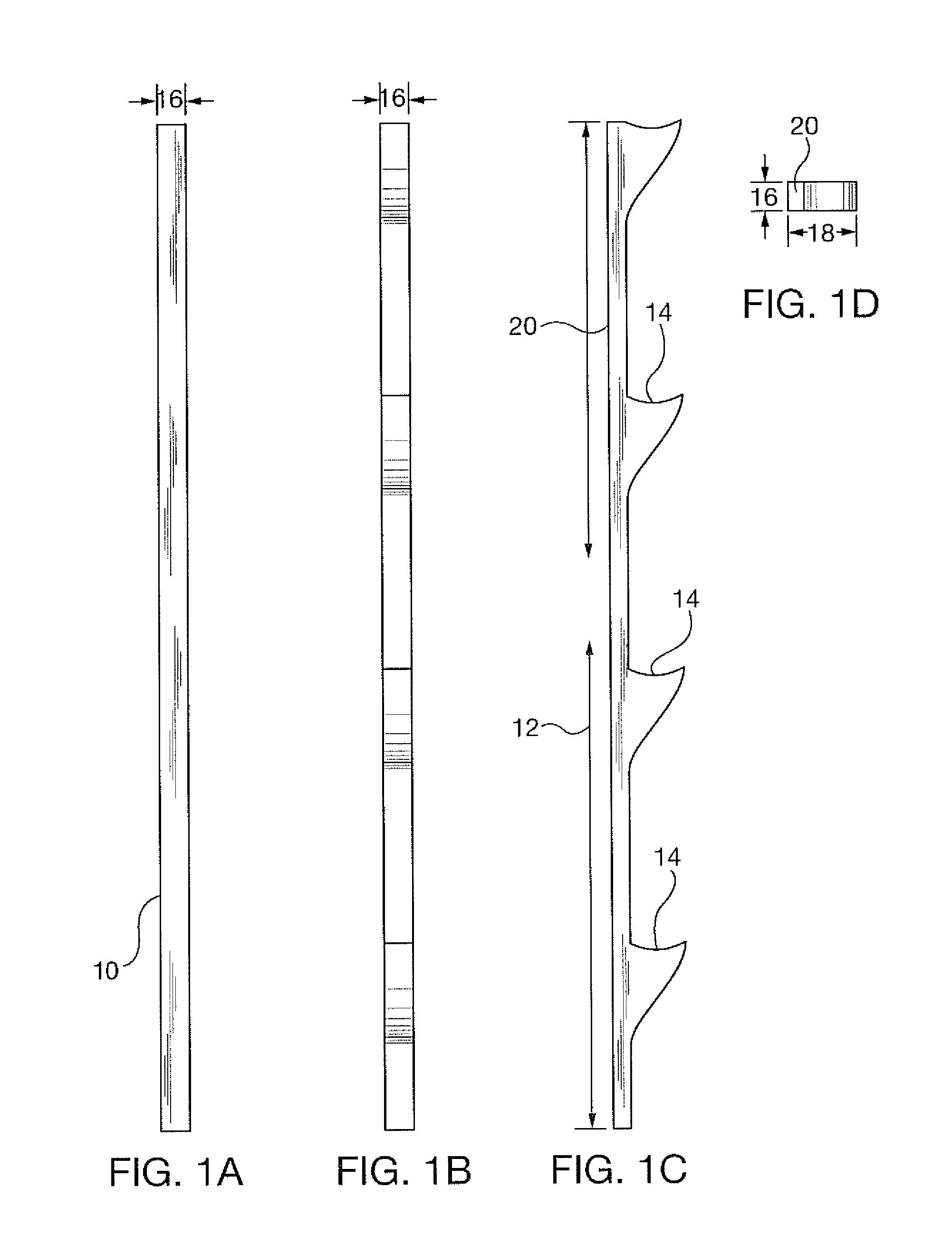
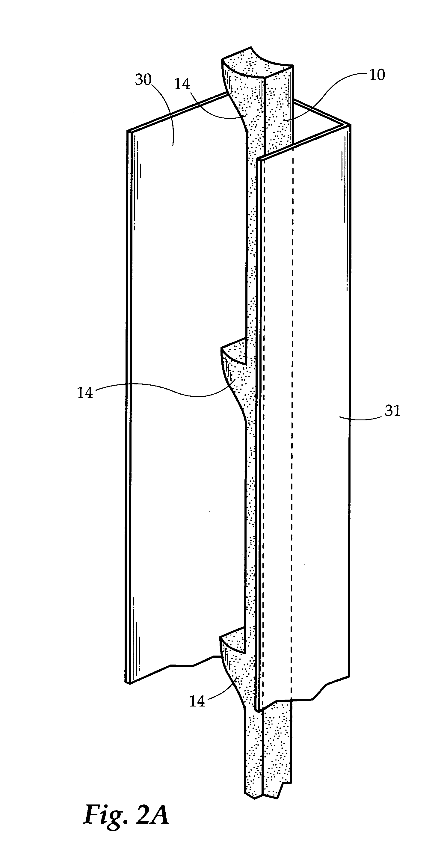
[0020]In FIGS. 1a-1d, the vinyl siding sealant of the invention is in the form of a moisture and vapor barrier strip—preferably of a polymeric rubber material of either natural or synthetic rubber—available as a strip cut from a roll of such material, for example. The strip 10 is of a length 12 selected to extend between bottom surfaces of adjacent vertically positioned parallel running vinyl siding pieces or panels. Ledge portions 14 of the strip 10, in this respect, are upwardly angled to receive the bottom surfaces of each vinyl siding piece—with the depiction of FIGS. 1a-1d being that which is based upon a double-dutch lap vinyl siding as commonly installed on a home as an attractive, durable and exterior alternative to the use of wood or similar types of siding. The front view of the strip as shown in FIG. 1a and the rear view as shown in FIG. 1b illustrate the width of the moisture and vapor barrier strip 10 as 16, with the top view of FIG. 1d likewise showing the width as 16,...


PUM

PropertyMeasurementUnit
Lengthaaaaaaaaaa
Thicknessaaaaaaaaaa
Widthaaaaaaaaaa

Abstract

A moisture and vapor barrier strip of polymeric rubber material of preselected length, width and thickness is inserted between gaps of vinyl siding panels on each level of a home vinyl installation to restrict the passage of air, rain and snow around the vinyl siding panels into the interior of the home as weather conditions change.

Description

CROSS-REFERENCE TO RELATED APPLICATIONS[0001]None.STATEMENT REGARDING FEDERALLY SPONSORED RESEARCH OR DEVELOPMENT[0002]Research and development of this invention and application have not been federally sponsored, and no rights are given under any Federal program.REFERENCE TO A MICROFICHE APPENDIX[0003]NOT APPLICABLEBACKGROUND OF THE INVENTION[0004]1. Field of the Invention[0005]This invention relates to vinyl siding attachments to the outer surface of a house, and, more particularly, to a barrier for restricting the passage of rain, snow and moisture in general into the interior of a home.[0006]2. Description of the Related Art[0007]As is known and understood, vinyl siding has become more and more popular among homeowners because of the advantages it offers over other exterior wall solutions. As an attractive, durable and exterior solution to the use of wood or similar types of siding, one feature of the vinyl siding installation is its elimination of painting and maintenance headac...

Claims


Application Information

Patent Timeline
IPC IPC(8): E04C2/38E04C2/20
CPCE04F13/0803E04F19/064E04F13/18
Inventor LEDGERWOOD, GARY L.
Owner LEDGERWOOD GARY L
Why Eureka
Try Eureka