Rotary wing aircraft having a tail rotor, and a method of optimizing the operation of a tail rotor

a technology of tail rotor and rotary wing aircraft, which is applied in the direction of propellers, mechanical equipment, transportation and packaging, etc., can solve the problems of increasing additional constraints, tail rotor running the risk of presenting efficiency, and the options available for dimensioning remain restricted, so as to minimize the noise emitted by the tail rotor, optimize fuel consumption or flight duration, and maximize energy efficiency

Inactive Publication Date: 2013-10-10
EUROCOPTER
View PDF7 Cites 54 Cited by
  • Summary
  • Abstract
  • Description
  • Claims
  • Application Information

AI Technical Summary

Benefits of technology

[0078]The setpoint thrust may be generated in order to minimize the noise emitted by the tail rotor, in order to optimize fuel consumption, or flight duration, or in order to maximize energy efficiency, for example.
[0079]In a variant, the pilot has the option of selecting regulation relationships as a function of an objective the pilot seeks to reach. During a flight over a densely populated area, the pilot may for example select regulation relationships that seek to limit noise emission, whereas in sparsely populated areas the pilot may select regulation relationships that enhance energy efficiency, for example.

Problems solved by technology

These accessories thus give rise to additional constraints.
However, the tail rotor then runs the risk of presenting efficiency that is not optimized during other stages of flight.
Nevertheless, it can be understood that the options available for dimensioning remain restricted.
Nevertheless, it appears to be difficult to make use of an electric motor.
While the electric motor is accelerating, the speed of rotation of the electric motor then runs the risk of exceeding the setpoint speed before it stabilizes at a value that is substantially equal to the setpoint speed.
Such inertia can be harmful for countering a sudden violent gust of wind.

Method used


Image

  • Rotary wing aircraft having a tail rotor, and a method of optimizing the operation of a tail rotor
  • Rotary wing aircraft having a tail rotor, and a method of optimizing the operation of a tail rotor

Examples


first embodiment

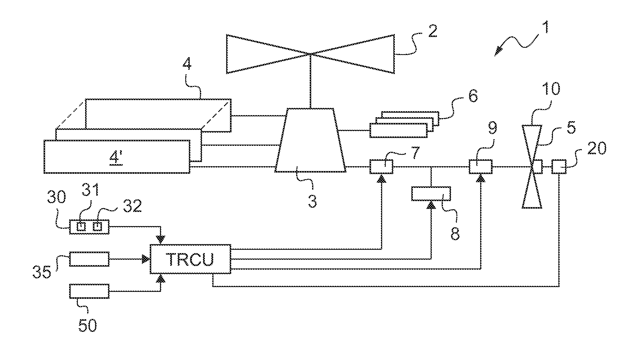
[0095]FIG. 1 thus shows a rotary wing aircraft 1 in a

[0096]Independently of the embodiment, the aircraft 1 has a power plant 4. This power plant 4 is fitted with at least one engine, and in particular a fuel burning engine 4′.

[0097]The power plant 4 then drives a main power transmission gearbox 3. The main power transmission gearbox 3 drives rotation of a main rotor 2 for providing lift and possibility also propulsion, and forming part of the rotary wing of the aircraft. The aircraft 1 may thus of the helicopter type.

[0098]The main power transmission gearbox may also drive accessories 6.

[0099]Furthermore, the aircraft 1 has an anti-torque tail rotor 5. The tail rotor 5 includes a plurality of blades 10 for opposing the torque generated by the main rotor 2 on the fuselage of the aircraft (not shown).

[0100]The pitch I of the blades 10 is variable. Under such circumstances, the aircraft includes a control device 20 for modifying this pitch of the blades 10 in flight on order from contr...

second embodiment

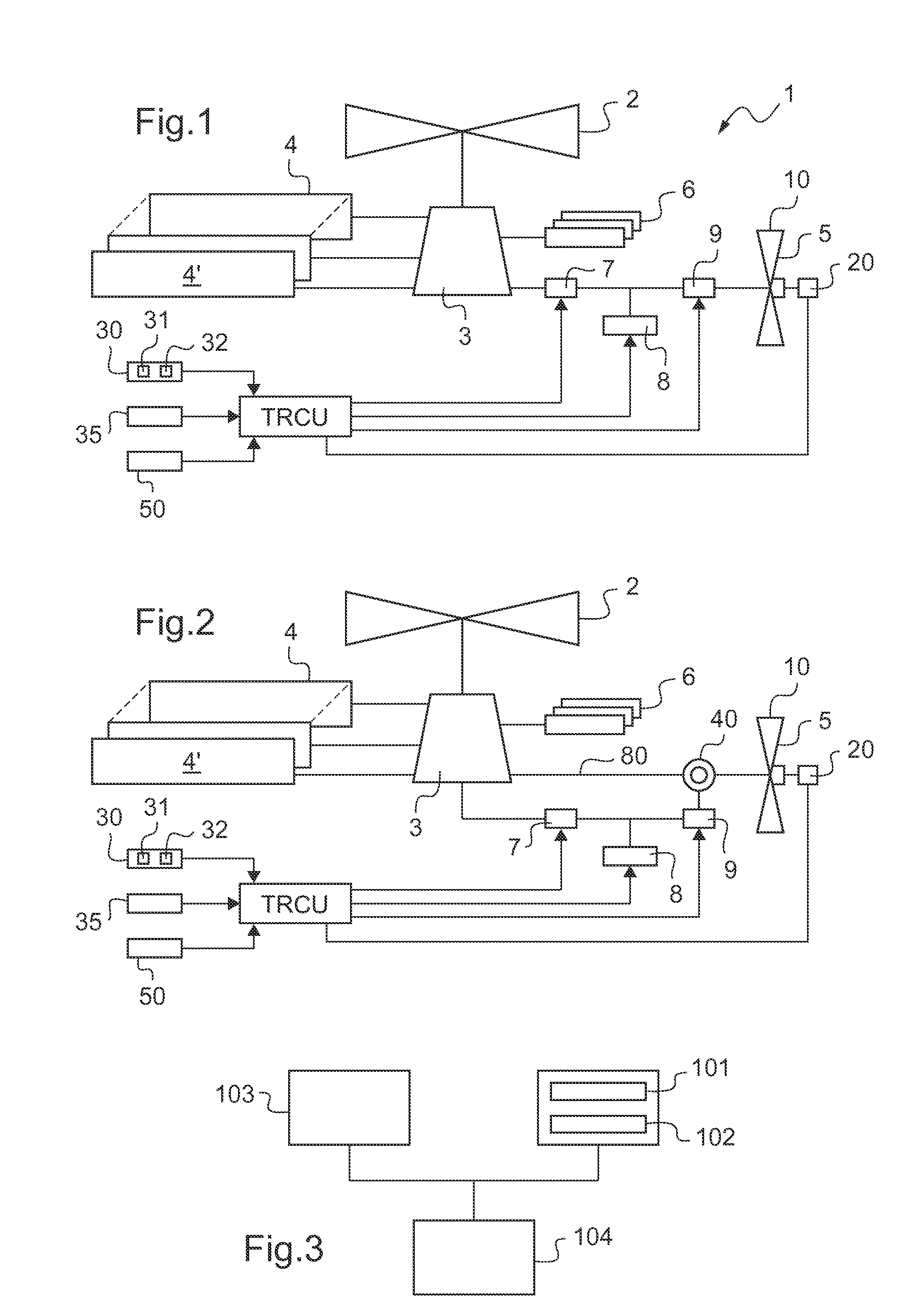
[0131]In the second embodiment, a differential system 40 is arranged between the electric motor 9 and the tail rotor 5.

[0132]A mechanical transmission 80 is then arranged in parallel with the electric motor 9 between the differential system 40 and the main power transmission gearbox 3.

[0133]The tail rotor may thus be driven mechanically by the main power transmission gearbox 3 and / or electrically by the electric motor 9.


PUM


Abstract

A rotary wing aircraft (1) provided with a main lift rotor (2), a tail rotor (5), and a power plant (4) driving a main gearbox (3) that co-operates with said main rotor (2), said tail rotor (5) being provided with a plurality of blades (10) of variable pitch (I) and with a pitch modification device (20), and said aircraft (1) having control means (30) for controlling said pitch modification device (20). The aircraft (1) includes an electric motor (9) for rotating said tail rotor (5) and regulator means (TRCU) connected to the control means (30) and also to the electric motor (9) and to the pitch modification device (20). The regulator means (TRCU) generate a first setpoint concerning pitch that is transmitted to the pitch modification device (20), and a second setpoint for controlling a motor parameter that is transmitted to the electric motor (9).

Description

CROSS REFERENCE TO RELATED APPLICATIONS[0001]This application claims priority to French patent application No. FR 12 00502 filed on Feb. 21, 2012, the disclosure of which is incorporated in its entirety by reference herein.BACKGROUND OF THE INVENTION[0002](1) Field of the Invention[0003]The present invention relates to a rotary wing aircraft provided with a tail rotor, and to a method of optimizing the operation of a tail rotor.[0004]More particularly, the invention lies in the technical field of rotary wing aircraft that include an anti-torque tail rotor. The tail rotor serves to oppose the torque exerted by the main rotor on the fuselage, and it also serves to control the aircraft in yaw.[0005](2) Description of Related Art[0006]Conventionally, a rotary wing aircraft may have a power plant driving both a main lift rotor and an anti-torque tail rotor in rotation. Such an aircraft may have a mechanical transmission including a main power transmission gearbox (MGB) interposed between...

Claims


Application Information

Patent Timeline
Patent Type & Authority Applications(United States)
IPC IPC(8): B64C27/82
CPCB64C27/82B64C2027/8209F15B2211/40507F15B2211/415F15B2211/41572B64C27/54B64D41/00
Inventor DYRLA, NADINE
Owner EUROCOPTER
Why Eureka
Try Eureka