Method for operating an electric fuel pump

a fuel pump and electric technology, applied in the direction of electric control, fuel injection control, machines/engines, etc., can solve the problems of reducing preventing reliable fuel delivery, and greatly delayed delivery and pressure buildup of the electric fuel pump, so as to delay the start of the internal combustion engine , reduce the efficiency of the latter, and prevent reliable fuel delivery

Active Publication Date: 2019-02-14
ROBERT BOSCH GMBH
View PDF36 Cites 0 Cited by
  • Summary
  • Abstract
  • Description
  • Claims
  • Application Information

AI Technical Summary

Benefits of technology

[0008]Vapor in the electric fuel pump can greatly reduce the latter's efficiency and can prevent reliable delivery of fuel. Only when a pump impeller of the electric fuel pump is once again surrounded by liquid fuel can it provide its full pumping effect. For this, however, firstly the vapor must be displaced out of the electric fuel pump. In extreme cases this can take several seconds. With the delayed pressure buildup of the electric fuel pump, startup of the internal combustion engine combustion is thus delayed. This is disadvantageous in particular when a quick departure is desired or stipulated by the driver. The consequence can be power loss, faltering, or stalling of the internal combustion engine. The high-pressure reservoir and the quantity of compression contained therein can meet the fuel demand of the internal combustion engine for a certain time, but the high pressure then collapses to insufficient values, and the injection quantities for the fuel injectors can no longer be outputted as desired. As a design measure, a venting valve to assist the removal of vapor from the electric fuel pump can also, for example, inter alia be used on the in-tank unit, but this results in additional cost. This furthermore does not ensure complete avoidance of delayed pressure buildup.
[0009]The invention takes effect here, by the fact that the electric fuel pump is operated even during such a stop phase. This prevents the electric fuel pump from being emptied during the stop phase due to excessive vapor pressure in the fuel tank. Aside from this, operation of the electric fuel pump also largely prevents the formation of vapor in the first place. This prevents any delay in restarting the internal combustion engine, and the further problems associated therewith. In addition, however, noise emissions during the stop phase are minimized by the fact that the electric fuel pump is operated with a minimum value for the relevant control application variable, i.e. a minimum possible value. Reference may be made to the statements below regarding appropriate values for the minimum value. The overall result of the proposed method is therefore to make possible rapid restarting of the internal combustion engine after a low-noise stop phase, without using additional components.
[0010]Advantageously, the electric fuel pump is operated for the time period at the minimum value only upon exceedance of a threshold value for a pressure and / or a temperature in a fuel tank in which the electric fuel pump is disposed, and is otherwise switched off. As already mentioned, emptying of the electric fuel pump during the stop phase is caused by the vapor pressure in the fuel tank. Since such emptying occurs, however, only above a certain pressure in the fuel tank which in turn, at least also, depends on the temperature in the fuel tank, it is useful to operate the electric fuel pump even during the stop phase only when pressures or temperatures are sufficiently high. Unnecessary operation at low pressures or temperatures can thus be avoided, thereby e.g. saving energy.

Problems solved by technology

If temperatures in the fuel tank are high upon a restart, however, a problem can occur with a pressure buildup in the low-pressure system, namely when the temperature in the fuel tank is in the vicinity of the vapor pressure of the fuel being used.
As a result of vapor formation at and in the electric fuel pump, the latter can become emptied during the stop phase, i.e. fuel in the electric fuel pump is forced back by the vapor into the fuel tank or into the pre-supply cup of the in-tank unit, so that upon restarting of the electric fuel pump, delivery and pressure buildup by the electric fuel pump are greatly delayed.
Vapor in the electric fuel pump can greatly reduce the latter's efficiency and can prevent reliable delivery of fuel.
In extreme cases this can take several seconds.
With the delayed pressure buildup of the electric fuel pump, startup of the internal combustion engine combustion is thus delayed.
This is disadvantageous in particular when a quick departure is desired or stipulated by the driver.
The consequence can be power loss, faltering, or stalling of the internal combustion engine.
The high-pressure reservoir and the quantity of compression contained therein can meet the fuel demand of the internal combustion engine for a certain time, but the high pressure then collapses to insufficient values, and the injection quantities for the fuel injectors can no longer be outputted as desired.
As a design measure, a venting valve to assist the removal of vapor from the electric fuel pump can also, for example, inter alia be used on the in-tank unit, but this results in additional cost.
This furthermore does not ensure complete avoidance of delayed pressure buildup.
It is thereby possible to take into consideration, for example, the fact that a restart does not occur after every shutoff of the internal combustion engine, or it occurs, for example, only after a longer time period, so that further operation of the electric fuel pump, for example, would consume too much energy.
It may also be the case, however, that, a sufficient flow through suction jet pumps that may be present is not achieved even at zero delivery.

Method used


Image

  • Method for operating an electric fuel pump
  • Method for operating an electric fuel pump
  • Method for operating an electric fuel pump

Examples


Embodiment Construction

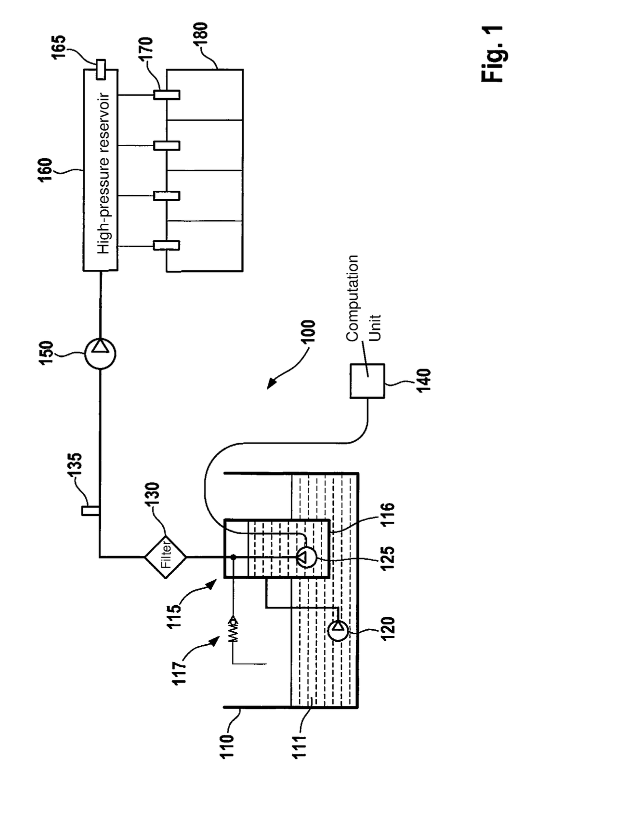
[0024]FIG. 1 schematically depicts a fuel supply system 100 for an internal combustion engine 180, which can be used for a method according to the present invention.

[0025]Fuel supply system 100 encompasses a fuel tank 110 that is filled with fuel 111. Located in fuel tank 110 is an in-tank unit 115 that in turn has a pre-supply cup 116 in which an electric fuel pump 125, operating as a low-pressure pump, is disposed.

[0026]Pre-supply cup 115 can be filled with fuel from fuel tank 110 via a suction jet pump 120 (or, if applicable, also several suction jet pumps) disposed in fuel tank 110 outside the pre-supply cup. Electric fuel pump 125 can have control applied to it via a computation unit 140 embodied here as a pump control device, so that fuel is delivered out of pre-supply cup 115 via a filter 130 to a high-pressure pump 150. A pressure limiting valve 117 is provided in the low-pressure line.

[0027]A pressure sensor 135 for detecting the pressure in the low-pressure line is provide...


PUM


Abstract

A method is described for operating an electric fuel pump constituting a low-pressure pump in a fuel supply system for an internal combustion engine, having a high-pressure reservoir and a high-pressure pump, of a motor vehicle. The electric fuel pump is operated at least temporarily, during a time period during which the internal combustion engine is switched off during operation of the motor vehicle, with a minimum value for a control application variable for the electric fuel pump.

Description

FIELD OF THE INVENTION[0001]The present invention relates to a method for operating an electric fuel pump and to a computation unit and a computer program for carrying it out.BACKGROUND INFORMATION[0002]In modern motor vehicles having internal combustion engines, one or more electric fuel pumps, in particular in the form of so-called “pre-supply” pumps, by way of which fuel is conveyed out of a fuel tank to a high-pressure pump, are used in the low-pressure fuel system, i.e. in the low-pressure region of the fuel supply system.[0003]The advantages of rapid availability thanks to pre-delivery of fuel by an electric fuel pump are thereby combined with the advantages of the hydraulic efficiency of a high-pressure pump driven by the internal combustion engine. Fuel delivery can furthermore be effected in accordance with demand. An electric fuel pump (EFP) as a rule requires a separate control system or regulation system, and has for that purpose an electronic system that, for example, c...

Claims


Application Information

Patent Timeline
Patent Type & Authority Applications(United States)
IPC IPC(8): F02D41/30F02D41/38F02D41/06
CPCF02D41/3082F02D41/3854F02D41/064F02D41/065F02D2200/0604F02D2200/0608F02D2200/70F02D2200/501F02D2200/0611F02D41/042
Inventor KUEMPEL, JOERGJOOS, KLAUS
Owner ROBERT BOSCH GMBH
Why Eureka
Try Eureka