Aircraft door installation

a technology for installing airframe doors and exterior doors, which is applied in the direction of construction fastening devices, applications for locking, transportation and packaging, etc., can solve the problem of unfavorable rear door vibration

Inactive Publication Date: 2013-10-10
AIRBUS OPERATIONS (SAS)
View PDF7 Cites 8 Cited by
  • Summary
  • Abstract
  • Description
  • Claims
  • Application Information

AI Technical Summary

Benefits of technology

[0009]d) continuing to rotate the door away from the airframe over a non-damped opening range to the open angle, wherein the damper does not damp the motion of the door as it rotates over the non-damped opening range.
[0010]A second aspect of the invention provides an aircraft exterior door installation comprising a door pivotally attached to an airframe, a damper which is arranged to damp the motion of the door as it is opened by rotating it away from the airframe; and a coupling mechanism which is arranged to couple the damper with the door over an opening damping range and decouple the damper from the door at the end of the opening damping range so that the damper does not damp the motion of the door as it opens further beyond the opening damping range.
[0011]It has been found that the vibration described in FR 2957052 A1 is only significant over a limited range of motion of the door. Therefore instead of damping the door over its full range of motion, it is only damped over a limited inner range. This enables the damping mechanism to be compact and light whilst also permitting the door to open over a large angular range (which may be over 120° or as much as 145°) without being impeded by the damper. A further advantage of decoupling the door and the damper is that the damper does not need to extend into the airflow to the same extent as the door, thus minimising aerodynamic drag.
[0023]Typically the damper has a first end pivotally attached to a coupling member and a second end pivotally attached to the airframe. The coupling member is pivotally attached to the airframe, and the door applies a force to the coupling member (either directly or via a fitting carried by the inner face of the door panel) which causes the coupling member to rotate on its pivot, rotation of the coupling member causing the damper to change in length and damp the motion of the door.
[0024]Typically the motion of the door during damping causes the damper to move (for instance by rotating) from a first position to a second position. The damper may remain in its second position after it has decoupled with the door. However more preferably the method further comprises returning the damper back to its first position after the door and the damper have been decoupled. By returning the damper in this way as the door opens, the aerodynamic drag of the decoupled damper is minimised. Returning the damper in this way as the door closes resets the damper for the next cycle of opening and closing of the door.
[0027]Preferably the damper is a hydraulic damper or dashpot which creates a damping effect by the viscous effect of forcing hydraulic fluid through a constriction. However other forms of damper may be used, for instance using eddy currents to create a force proportional to velocity.

Problems solved by technology

As described in FR 2957052 A1, such an arrangement can cause undesirable vibrations in the rear doors.

Method used


Image

  • Aircraft door installation
  • Aircraft door installation
  • Aircraft door installation

Examples


Embodiment Construction

)

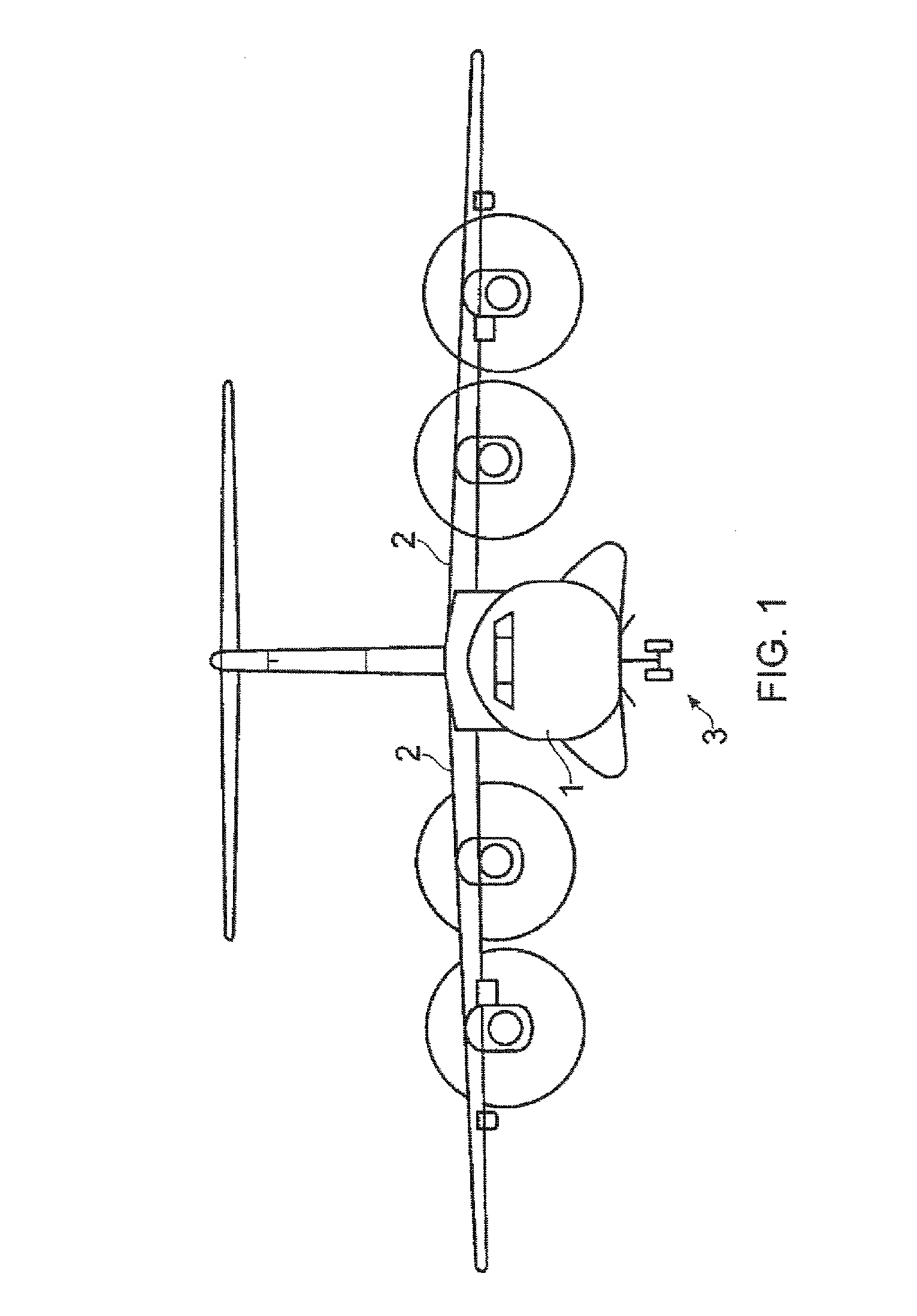
[0041]An aircraft shown in FIG. 1 has an airframe comprising a fuselage 1 and a pair of wings 2. The fuselage 1 has a nose landing gear 3 shown in FIG. 1 in its lowered position.

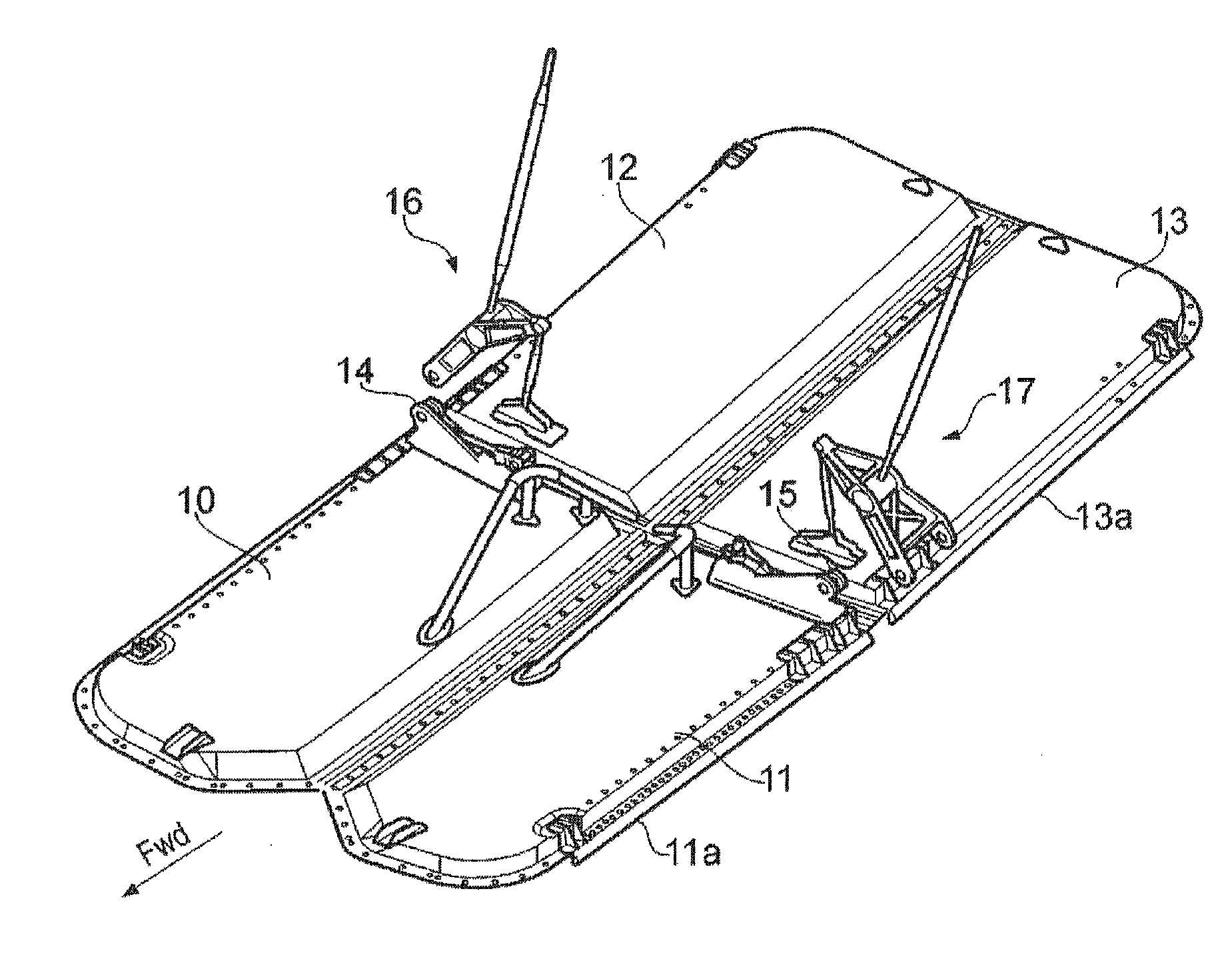
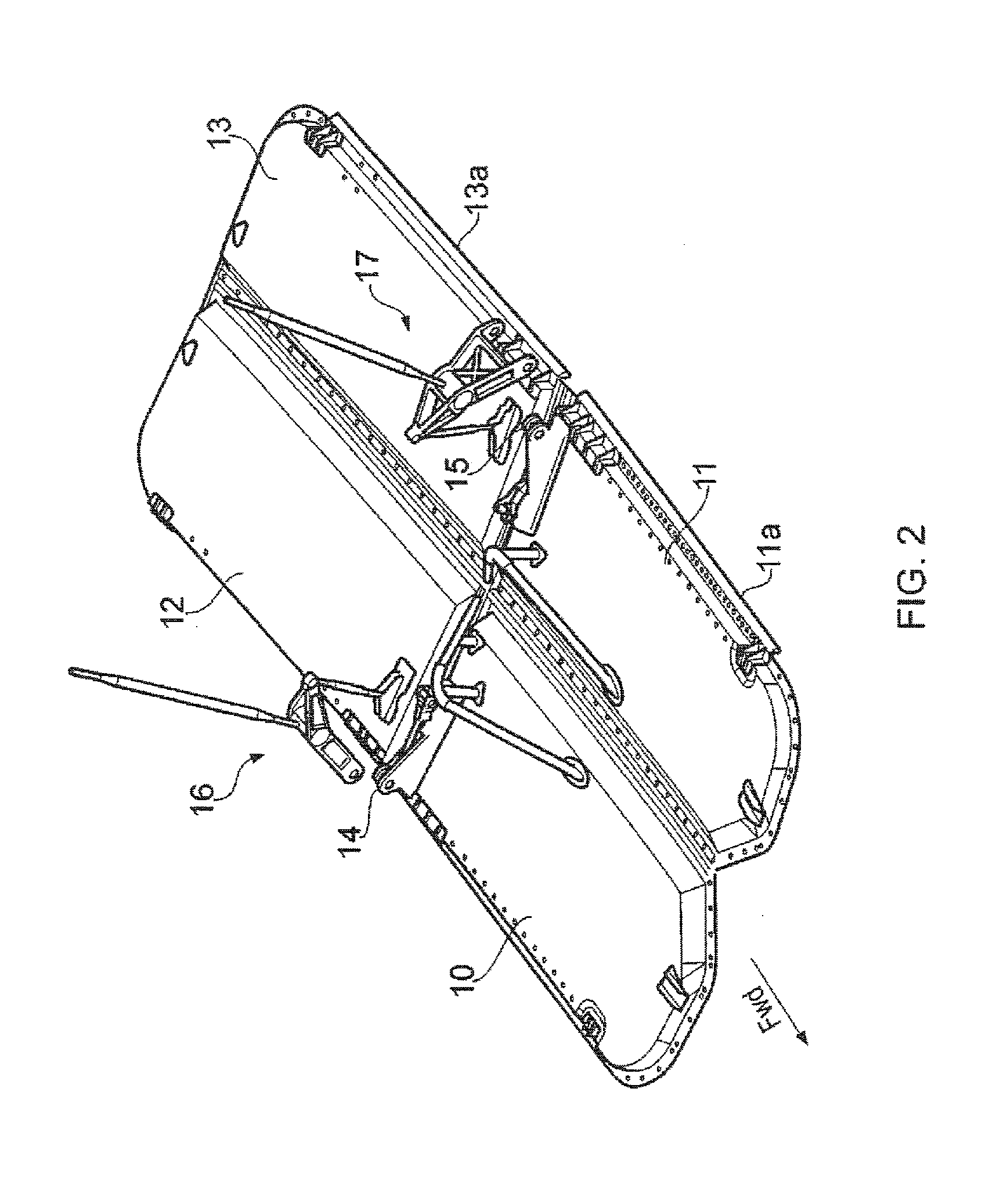
[0042]During cruise of the aircraft the landing gear is housed in a landing gear bay which is closed by four landing gear bay doors 10-13 shown in FIG. 2, each of which is pivotally attached to the fuselage by a hinge 11a,13a at its outer edge so it can be rotated down from its closed position shown in FIG. 2 to its open position.

[0043]Prior to lowering the landing gear 3 the pair of forward doors 10,11 are opened to about 120° by hydraulic actuators (not shown) attached to fittings 14,15. The landing gear is then lowered, and as it does so the motion of the landing gear causes the rear doors 12,13 to open at the same time via a kinematic linkage mechanism 16,17 attached to each rear door. The forward doors 10,11 are then closed. This sequence is then reversed when the landing gear is raised after takeoff. ...


PUM


Abstract

An aircraft exterior door installation with a door attached to an airframe. A damper is arranged to damp motion of the door as it is opened by rotating it away from the airframe. A coupling mechanism couples the damper with the door over an opening damping range and decouples the damper from the door at the end of the opening damping range. The damper does not damp the motion of the door as it opens beyond the opening damping range. Instead of damping the door over its full range of motion, it is only damped over a limited inner range of its motion. A further advantage of decoupling the door and the damper is that the damper does not need to extend into the airflow to the same extent as the door, thus minimising aerodynamic drag.

Description

CROSS-REFERENCE TO RELATED APPLICATION[0001]This application claims priority to European Patent Application No. 12 161 567.8 filed on Mar. 15, 2012, the entire content of which is incorporated by reference herein.FIELD OF THE INVENTION[0002]The present invention relates to an aircraft exterior door installation comprising a door pivotally attached to an airframe, and a method of operating such an installation to damp the motion of the door. Preferably, although not exclusively, the installation is a landing gear door installation. The invention also relates to a damping mechanism suitable for use in such an installation.BACKGROUND OF THE INVENTION[0003]A known landing gear door installation is described in US 2011 / 0127376 A1. The landing gear compartment is closed by several doors: front doors which open during the descent of the gear, in particular to allow the leg thereof to pass, and close after the exit of the gear so as to preserve the aerodynamic shape of the fuselage of the a...

Claims


Application Information

Patent Timeline
Patent Type & Authority Applications(United States)
IPC IPC(8): B64C1/14
CPCB64C1/1407B64C25/16E05B77/00
Inventor VEERABADRAN, KAROUNEN
Owner AIRBUS OPERATIONS (SAS)
Why Eureka
Try Eureka