Circuit for protecting an electric load from overvoltages

a technology for protecting electrical loads and circuits, applied in the direction of electric variable regulation, process and machine control, instruments, etc., can solve the problems of high power supply load, approx. voltage drop, and the risk of electrical consumers being destroyed, so as to achieve low voltage dissipation, low cost and circuit complexity, and minimal voltage dissipation

Inactive Publication Date: 2013-10-10
INIT INNOVATIVE INFORMATIKANWENDUNGEN & TRANSPORT VERKEHRS UND LEITSYSTN
View PDF10 Cites 15 Cited by
  • Summary
  • Abstract
  • Description
  • Claims
  • Application Information

AI Technical Summary

Benefits of technology

[0014]It was first realized according to the invention that it is possible to achieve a protective circuit with a minimal voltage dissipation across the protective circuit, with relatively little increased cost and circuit complexity, even while using an n-channel MOSFET. To this end, an auxiliary voltage is used to control the gate of the MOSFET in such a manner that the MOSFET opens. In this case, it is possible to achieve particularly low voltage dissipation if the MOSFET is operated in the saturation region, and therefore is completely open.
[0015]For this purpose, a means for the generation of a reference voltage is connected to the gate of the MOSFET. The means generates a voltage which is dependent on the supply voltage at the input of the protective circuit, but which assumes at most an upper threshold which is the reference voltage. With this means, in most cases a voltage is set to ground. The reference voltage limits the voltage at the gate of the MOSFET. At the same time, the gate is connected to an auxiliary voltage source which supplies the gate with a voltage which is higher than the supply voltage applied at the input. In this way, the MOSFET is controlled beyond the linear region. In this manner, it is possible to completely take advantage of the benefits of the relatively cheap n-channel MOSFET, particularly with regard to the small constructed space and the improved transmission behavior compared to the p-channel MOSFET, without the need to accept associated high voltage dissipation across the protective circuit.

Problems solved by technology

Below this range, the electrical consumer switches off, while above this range, there is a risk of the electrical consumer being destroyed.
The cause of overvoltages is frequently a high load on the power supply—for example when a vehicle is started—or interruptions in the power supply when a failure occurs.
The causes of overvoltages are, by way of example, lightning strikes, switching operations occurring in the supply grid, power supplies being brought online, electrostatic discharges, or sudden load drops in the supply grid.
The problem with this circuit is that there is a voltage drop of approx.
This leads on the one hand to a relatively high dissipation loss, particularly at high load currents.
If the protective circuit is used for example in a motor vehicle, and the supply voltage is interrupted during a starting of the vehicle, this can result in a reset of the connected devices.
However, these MOSFETS are expensive, particularly for high load currents, and the circuits take up relatively large amounts of space.
However, these are highly restricted in most cases due to the basic specifications, such as the possible limit voltage or the possible current load.
If protection should be provided for limit voltages above 15 V only very few voltage regulators are available yet.

Method used


Image

  • Circuit for protecting an electric load from overvoltages
  • Circuit for protecting an electric load from overvoltages
  • Circuit for protecting an electric load from overvoltages

Examples


Embodiment Construction

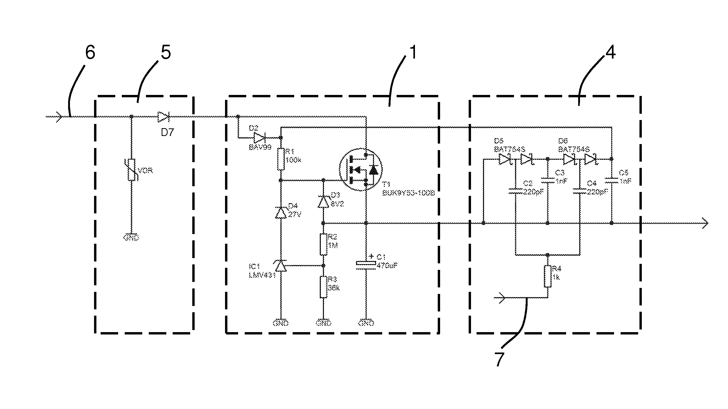
[0030]FIG. 4 shows a first embodiment of the protective circuit according to the invention. The protective circuit 1 is connected at the input 2 thereof to a voltage source, which is not included in the drawing, and is thereby supplied with a supply voltage Uin. The input 2 is connected to the drain of an n-channel MOSFET T1. The source of the MOSFET T1 is connected to the output 3 of the protective circuit 1. The gate of the MOSFET T1 is connected to the input 2 of the protective circuit 1 via a diode D2 and a resistor R1. In this manner, the gate is supplied with a voltage following the application of the supply voltage Uin, wherein the voltage is determined by the supply voltage Uin, the voltage drop across the diode D2 and the voltage drop across the resistor R1. The gate is further connected via a first Zener diode D1 to ground. The first Zener diode D1 is operated in the blocking direction, such that the gate is supplied at most with a voltage which is determined by the breakd...


PUM


Abstract

A circuit for protecting an electric load from overvoltages has an n-channel MOSFET (metal oxide semiconductor field-effect transistor) (T1) and a means for producing a reference voltage in order to achieve the most effective overvoltage protection possible by means of the cheapest and most compact circuit possible, wherein the means for producing a reference voltage is connected to the gate of the MOSFET (T1), wherein a supply voltage is applied to the circuit on the input side and wherein the gate is supplied with a voltage greater than the supply voltage using an auxiliary voltage source in such a way that the MOSFET (T1) is turned on.

Description

CROSS REFERENCE TO RELATED APPLICATIONS[0001]This application is a national stage application, filed under 35 U.S.C. §371, of International Application No. PCT / DE2011 / 050052, filed Dec. 5, 2011, which claims priority to and the benefit of German Application No. 10 2010 054 402.7, filed Dec. 14, 2010, the contents of both of which are hereby incorporated by reference in their entirety.BACKGROUND[0002]1. Technical Field[0003]The invention relates to a circuit for the protection of an electrical consumer against overvoltage.[0004]2. Description of Related Art[0005]Electrical consumers typically have a voltage range in which they can be safely operated. Below this range, the electrical consumer switches off, while above this range, there is a risk of the electrical consumer being destroyed. The cause of overvoltages is frequently a high load on the power supply—for example when a vehicle is started—or interruptions in the power supply when a failure occurs. A brief drop in voltage is co...

Claims


Application Information

Patent Timeline
Patent Type & Authority Applications(United States)
IPC IPC(8): H02H3/20
CPCH02H3/20G05F1/56
Inventor GUELTIG, MICHAEL
Owner INIT INNOVATIVE INFORMATIKANWENDUNGEN & TRANSPORT VERKEHRS UND LEITSYSTN
Why Eureka
Try Eureka