
Eureka
For R&D, Eureka makes reading and utilizing patents & technical documents easy.
Eureka AIR
Designed for self-driven R&D workflows. Generate viable solutions, solve complex R&D challenges, empower your innovation with AI.

Eureka Materials
Designed for material experts only. Revolutionize your material R&D, from search, analyze, to developing new materials.

TechResearch
Generate reliable direction feasibility study reports for your R&D in just a few steps.

TechSeek
Discover and master advanced knowledge NOW. Basics, ideas, possibilities, all at once.

TechMind
As an expert in R&D Theories, TechMind can generates customized viable solutions instantly.

TechRisk
Analyze your overall solution with one click, know your potential R&D risks in advance.

TechMonitor
Get weekly tech updates, stay abreast of the latest tech innovations and key insights.
Image forming apparatus
- Summary
- Abstract
- Description
- Claims
- Application Information
AI Technical Summary
Benefits of technology
Problems solved by technology
Method used
Image

Examples
embodiment 1
Image Forming Apparatus
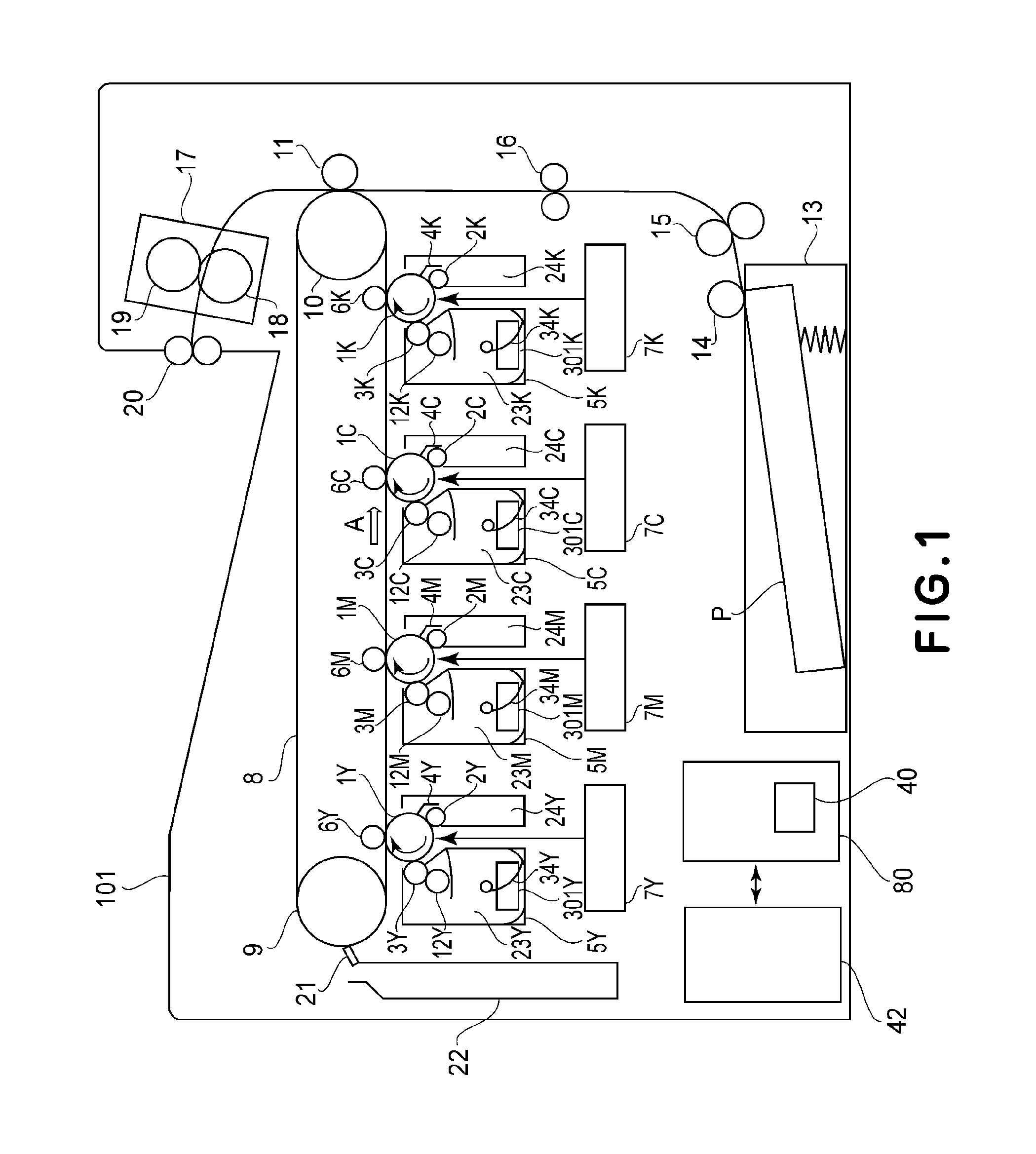
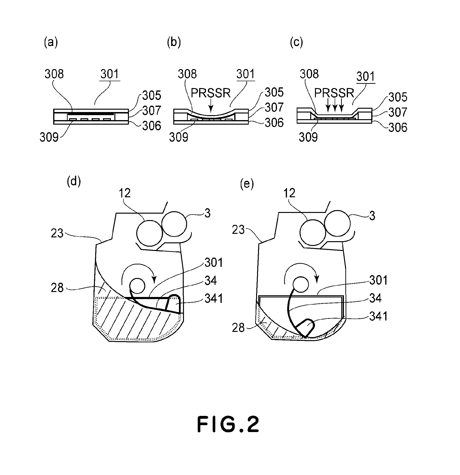
[0032]FIG. 1 is a sectional view showing a general structure of a color laser printer which is an example of an image forming apparatus in this embodiment, and a constitution and basic operation of the color laser printer will be described with reference to FIG. 1. The color laser printer (hereinafter referred to as a main assembly 101) includes process cartridges 5Y, 5M, 5C and 5K which are detachably mountable to the main assembly 101. These four process cartridges 5Y, 5M, 5C and 5K have the same structure but are different in that they form images with toners (developers) of yellow (Y), magenta (M), cyan (C) and black (K), respectively. Hereinafter, the suffixes Y, M, C and K will be omitted in some cases. The process cartridge 5 is constituted by 3 units consisting of a developing unit, an image forming unit and a residual toner unit. The developing unit includes a developing roller 3, a toner supplying roller 12, a toner container 23 and a polyester (tere...
embodiment 2
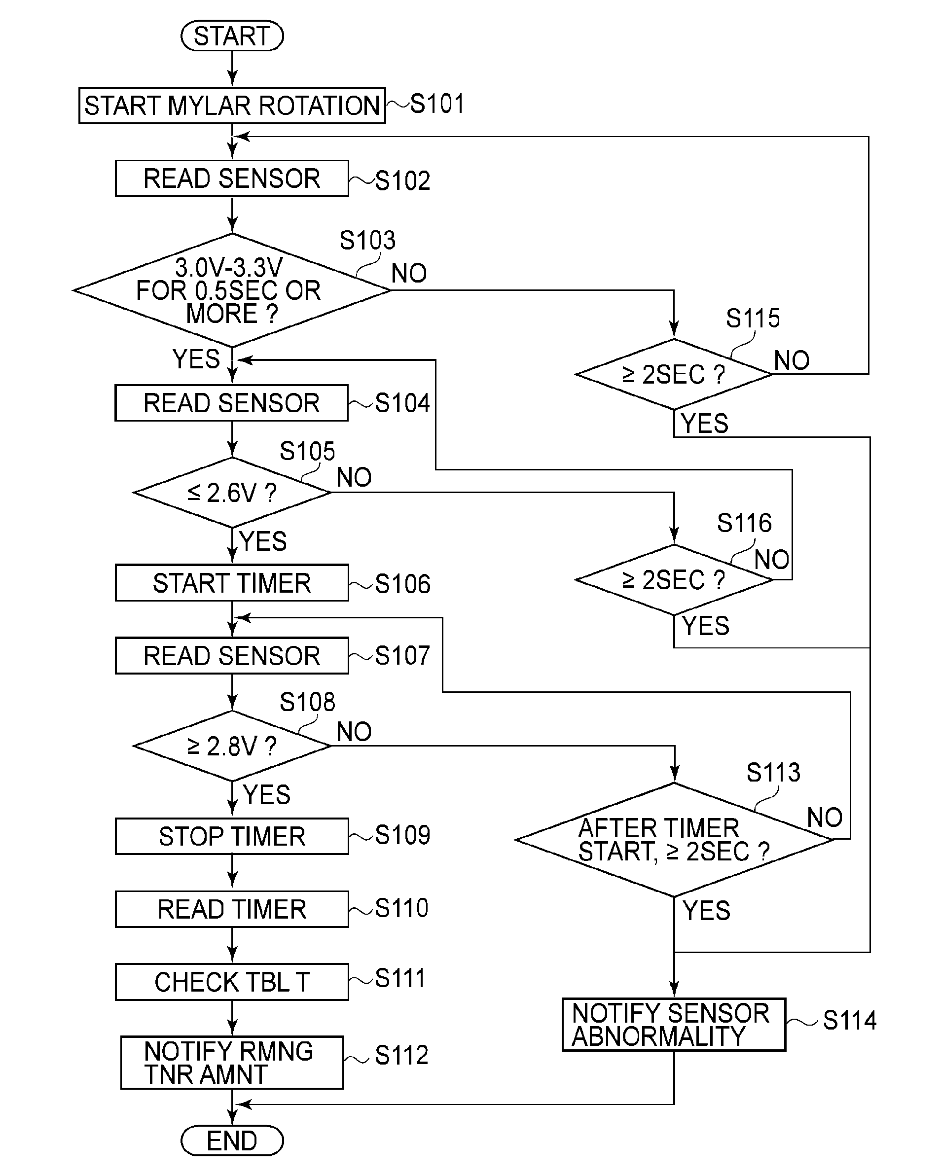
[0054]In Embodiment 1, on the basis of the time duration in which the pressure-sensitive resistance sensor 301 detects the pressure, the example in which the remaining toner amount is detected was described. In this embodiment, the resistance value of the pressure-sensitive resistance sensor 301 varies depending on the detected pressure and therefore an example in which the remaining toner amount is detected by detecting the change in voltage inputted into the A / D port of the CPU 40 will be described. Incidentally, the constitutions of FIGS. 1 to 3 and (a) of FIG. 4 described in Embodiment 1 are also applied to those in this embodiment. Further, the same constituent elements as those in Embodiment 1 are represented by the same reference numerals or symbols and are specifically described in Embodiment 1, thus being omitted from description in this embodiment.
[Detection Characteristic of Remaining Toner Amount]
[0055]Next, a detection characteristic of the remaining toner amount measur...
embodiment 3
[0061]In Embodiment 1, on the basis of the time in which the pressure-sensitive resistance sensor 301 detects the pressure, the remaining toner amount was detected. In this embodiment, in place of the pressure-sensitive resistance sensor 301, a sheet switch 311 which is a switch element is used and the remaining toner amount is detected on the basis of the time in which the sheet switch 311 detects the pressure. Further, with timing when the sheet switch 311 does not detect the pressure, temperature detection of the process cartridge 5 is effected and on the basis of detected temperature data, control of an unshown cooling fan or the like is effected. Further, a temperature detection signal is incorporated from the A / D port via the same signal line as that for the remaining toner amount detection data. Incidentally, the constitutions of FIGS. 1 to 3 described in Embodiment 1 are also applied to those in this embodiment. However, the sheet switch 311 has the same shape as the pressur...
PUM
 Abstract
Description
Claims
Application Information
 - R&D Engineer
- R&D Manager
- IP Professional
- Industry Leading Data Capabilities
- Powerful AI technology
- Patent DNA Extraction
Browse by: Latest US Patents, China's latest patents, Technical Efficacy Thesaurus, Application Domain, Technology Topic, Popular Technical Reports.
© 2024 PatSnap. All rights reserved.Legal|Privacy policy|Modern Slavery Act Transparency Statement|Sitemap|About US| Contact US: help@patsnap.com