Radial Neutron Reflector

a radial reflector and neutron reflector technology, applied in the field of nuclear power reactor arts and neutron reflector arts, can solve the problems of high radiation flux of welds, bolts or other fasteners of radial reflectors, prone to damage or failure, and neutrons originating near the outer boundary of the reactor core may travel outside the reactor core and be los

Active Publication Date: 2013-10-17
BWXT MPOWER INC
View PDF15 Cites 11 Cited by
  • Summary
  • Abstract
  • Description
  • Claims
  • Application Information

AI Technical Summary

Benefits of technology

[0006]According to one aspect, an apparatus comprises a nuclear reactor core comprising fissile material and a core former surrounding the nuclear reactor core. The core former comprises one or more single-piece annular rings wherein each single-piece annular ring comprises neutron-reflecting material. In some embodiments the core former comprises a stack of two or more single-piece annular rings wherein each single-piece annular ring comprises neutron-reflecting material. In some embodiments the stack of single-piece annular rings is self-supporting. In some embodiments the stack of single-piece annular rings does not include welds or fasteners securing adjacent single-piece annular rings together.
[0007]According to another aspect, an apparatus comprises a nuclear reactor core comprising fissile material, a core former surrounding the nuclear reactor core and including one or more single-piece annular rings wherein each single-piece annular ring comprises neutron-reflecting material, and a core basket containing the nuclear reactor core and the core former. In some embodiments an annular gap is defined between the core former and the core basket. In some embodiments an annular gap is defined between the core former and the core basket and the core form

Problems solved by technology

However, neutrons originating near the outer boundary of the reactor core may travel outside the reactor core and be lost.
The welds, bolts, or other fasteners of the radial reflector experience high radiation flux, and can be prone to damage or failure due to the harsh operating environment with the reactor.
Repair of any such damage is difficult or impossible due to the extremely radioact

Method used


Image

  • Radial Neutron Reflector
  • Radial Neutron Reflector
  • Radial Neutron Reflector

Examples


Embodiment Construction

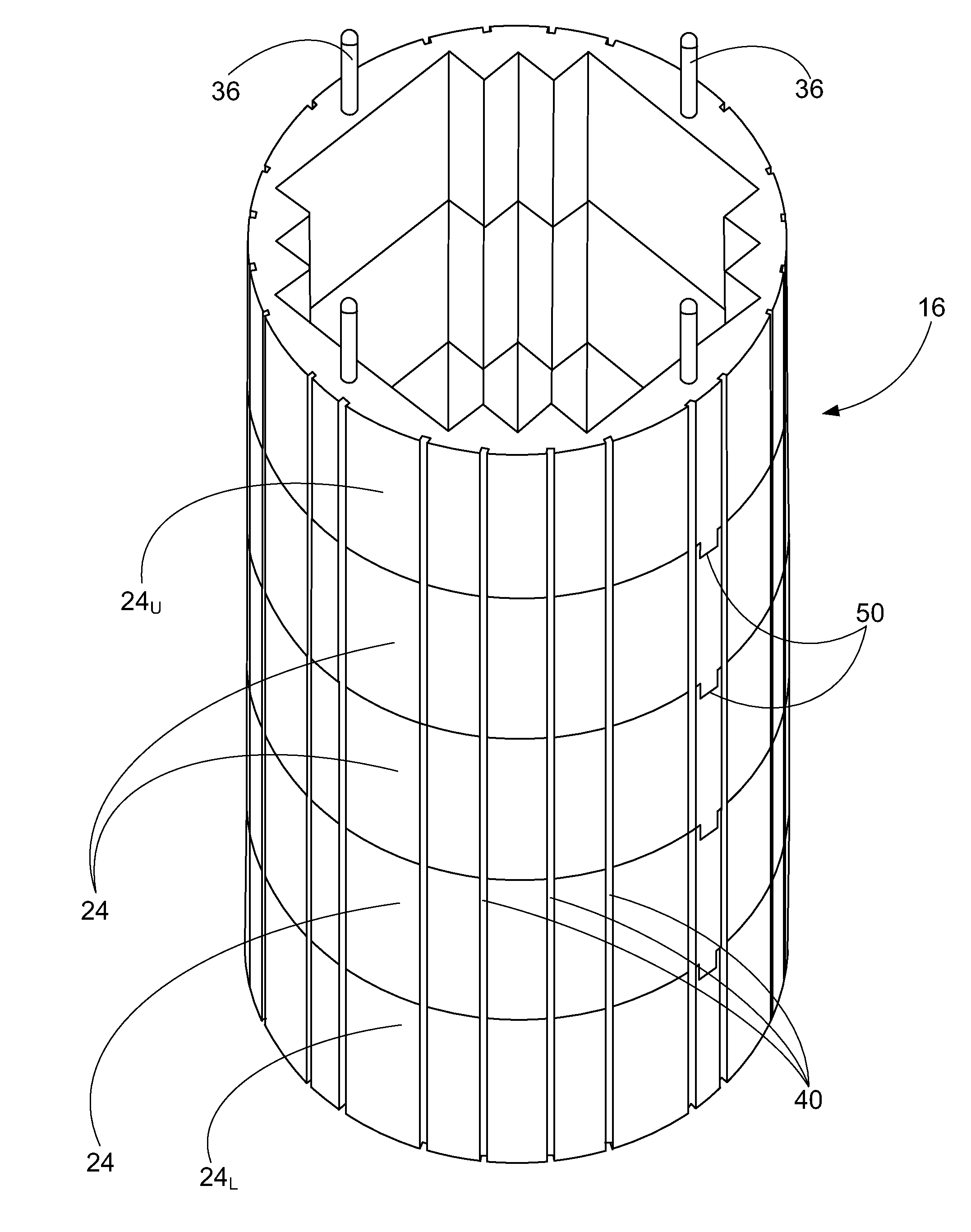
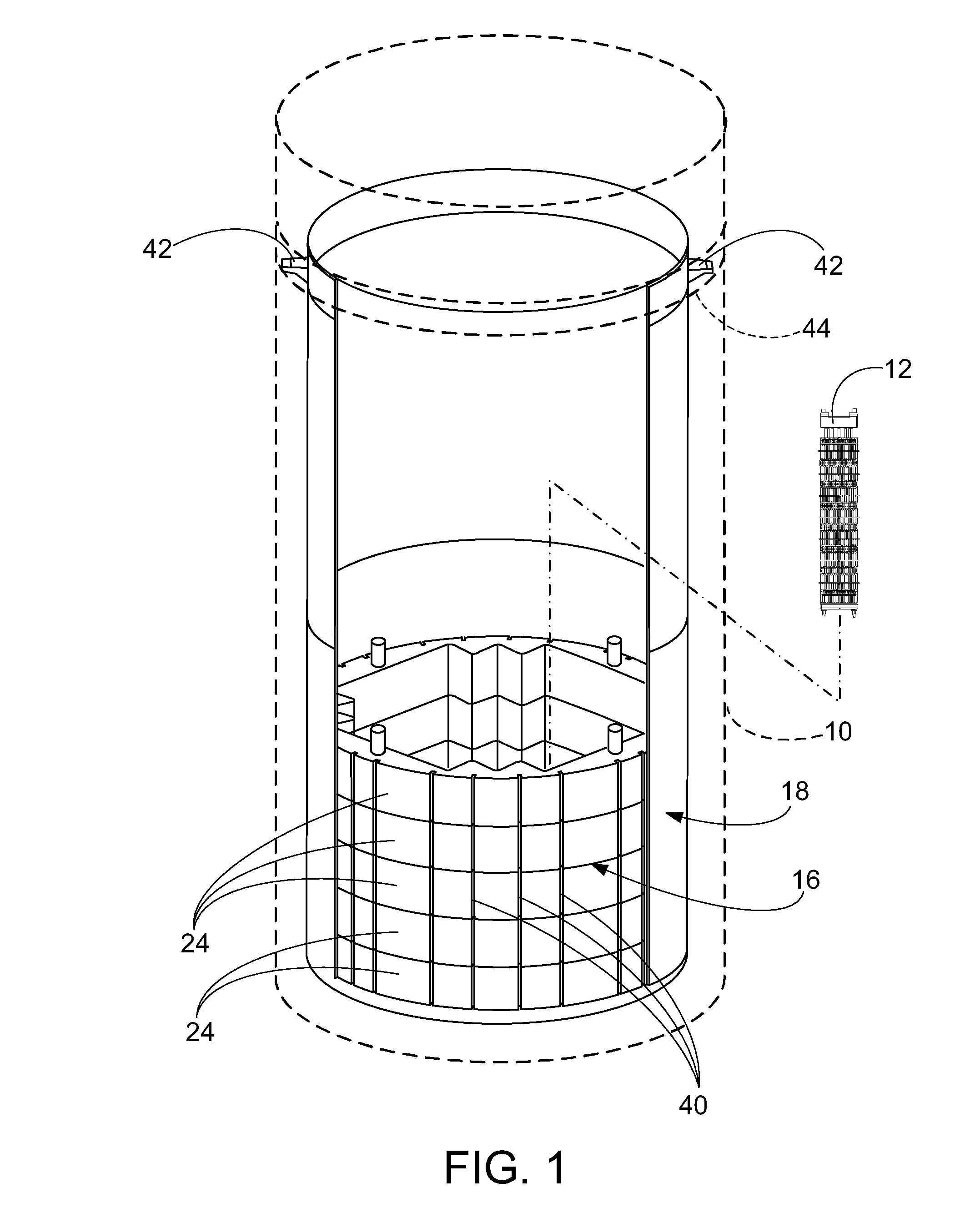
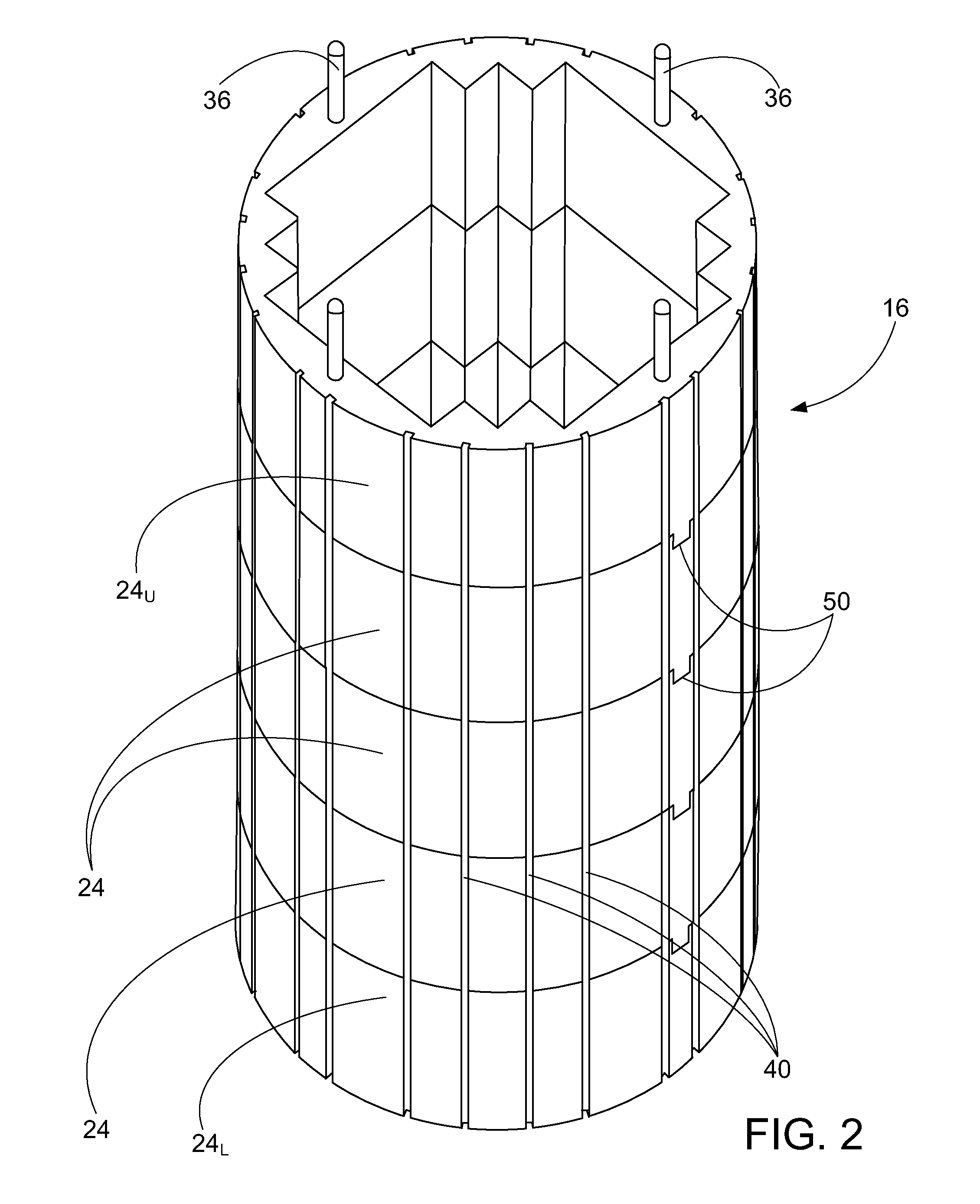
[0015]With reference to FIGS. 1-3, a core former as disclosed herein is described in the context of an illustrative nuclear reactor of the pressurized water reactor (PWR) type. The nuclear reactor includes a pressure vessel 10, only a lower portion of which is shown diagrammatically in phantom in FIG. 1. The lower portion of the pressure vessel contains a reactor core constructed as an array of fuel assemblies. For illustrative purposes, FIG. 1 shows a single fuel assembly 12 being loaded into the reactor. (The loading is done using a crane or other lifting apparatus, not shown). The fuel assembly 12 is shown diagrammatically, and typically includes a structural skeleton of spacer grids and upper and lower end fittings or nozzles supporting the fuel rods with guide tubes interspersed amongst the fuel rods to provide conduits for control rods, instrumentation, or the like (details not illustrated). FIG. 3 shows an overhead or top view including the complete nuclear reactor core 14 co...


PUM


Abstract

A nuclear reactor core comprising fissile material is surrounded by a core former. The core former comprises one or more single-piece annular rings wherein each single-piece annular ring comprises neutron-reflecting material. In some embodiments the core former comprises a stack of two or more such single-piece annular rings. In some embodiments the stack of single-piece annular rings is self-supporting. In some embodiments the stack of single-piece annular rings does not include welds or fasteners securing adjacent single-piece annular rings together. A core basket may contain the nuclear reactor core and the core former, and in some embodiments an annular gap is defined between the core former and the core basket. In some embodiments the core former does not include welds and does not include fasteners.

Description

[0001]This application claims the benefit of U.S. Provisional Application No. 61 / 623,332, filed Apr. 12, 2012. U.S. Provisional Application No. 61 / 623,332, filed Apr. 12, 2012 is hereby incorporated by reference in its entirety into the specification of this application.BACKGROUND[0002]The following relates to the nuclear power reactor arts, neutron reflector arts, and related arts.[0003]In a nuclear reactor, fissile material is arranged in the reactor such that the neutron flux density resulting from fission reactions is sufficient to maintain a sustained fission process. In a commercial reactor, fissile material is typically provided in the form of fuel rods mounted in modular, elongated fuel assemblies which are generally square or hexagonal in cross section. A plurality of such fuel assemblies are arranged together to form a reactor core which is contained inside a cylindrical stainless steel core basket. This entire assembly, in turn, is mounted inside a pressure vessel. In a t...

Claims


Application Information

Patent Timeline
IPC IPC(8): G21C5/00G21C19/00
CPCG21C5/02G21C11/06G21F3/04Y02E30/30
Inventor WHITTEN, ANDREW C.EDWARDS, MICHAEL J.ALES, MATTHEW W.
Owner BWXT MPOWER INC
Why Eureka
Try Eureka