Pressurized water reactor with upper plenum including cross-flow blocking weir

Active Publication Date: 2013-05-16
BWXT MPOWER INC +1
View PDF5 Cites 11 Cited by
  • Summary
  • Abstract
  • Description
  • Claims
  • Application Information

AI Technical Summary

Problems solved by technology

However, in some reactor designs this natural convection is augmented or supp

Method used


Image

  • Pressurized water reactor with upper plenum including cross-flow blocking weir
  • Pressurized water reactor with upper plenum including cross-flow blocking weir
  • Pressurized water reactor with upper plenum including cross-flow blocking weir

Examples


Embodiment Construction

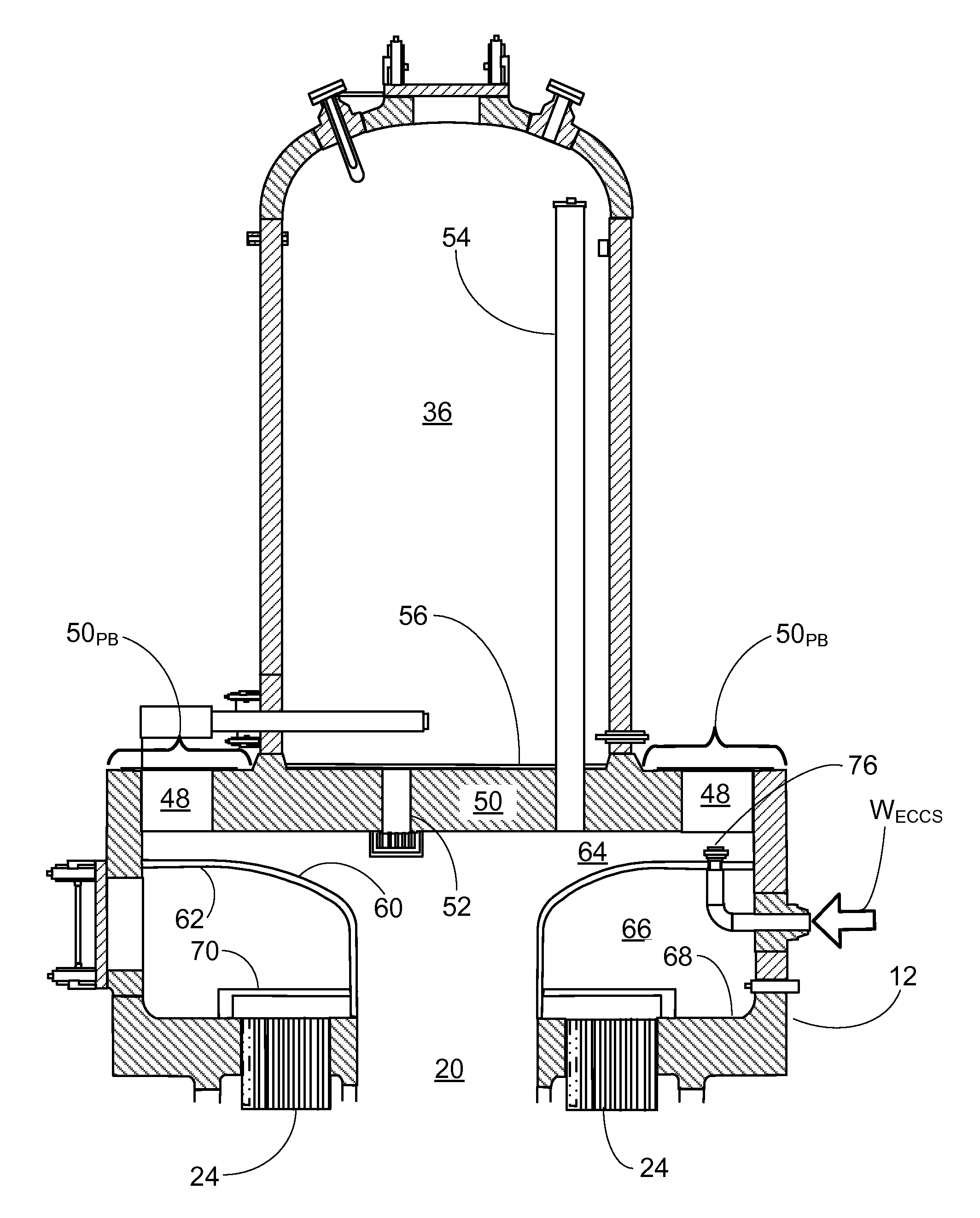
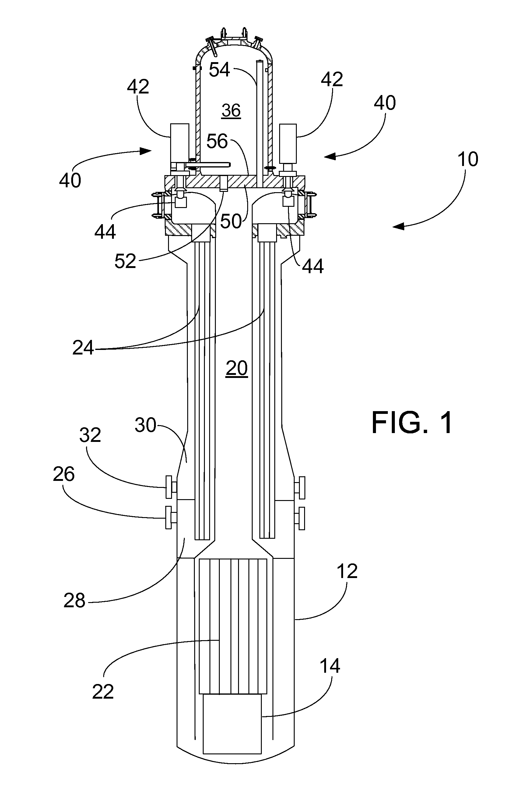
[0021]With reference to FIG. 1, an illustrative nuclear reactor of the integral pressurized water reactor (integral PWR) type 10 includes a pressure vessel 12, which in the illustrative embodiment is a vertically mounted cylindrical pressure vessel. As used herein, the phrase “cylindrical pressure vessel” or similar phraseology indicates that the pressure vessel has a generally cylindrical shape, but may in some embodiments deviate from a mathematically perfect cylinder. For example, the illustrative cylindrical pressure vessel 12 has a circular cross-section of varying diameter along the length of the cylinder, and has rounded ends, and includes various vessel penetrations, vessel section flange connections, and so forth. Similarly, although the pressure vessel 12 is upright, that is, vertically oriented, it is contemplated for the vertically oriented cylinder axis of the cylindrical pressure vessel to deviate from being precisely vertical respective to gravity. For example, if the...


PUM


Abstract

A pressurized water reactor (PWR) comprises: a nuclear core comprising a fissile material; a cylindrical pressure vessel having a vertically oriented cylinder axis and containing the nuclear core immersed in primary coolant water; and a hollow cylindrical central riser disposed concentrically with and inside the cylindrical pressure vessel. A downcomer annulus is defined between the hollow cylindrical central riser and the cylindrical pressure vessel. The hollow cylindrical central riser has a radially expanding upper orifice that merges into an annular divider plate that separates an upper plenum above the annular divider plate from a lower plenum below the annular divider plate. The upper plenum is in fluid communication with the radially expanding upper orifice and the lower plenum is in fluid communication with the downcomer annulus. A weir may extend away from a bottom wall of the lower plenum into the lower plenum. An emergency core cooling system (ECCS) return line nozzle may be arranged to inject water into the upper plenum. A pump support plate spans the inner diameter of the cylindrical pressure vessel and forms a portion of the pressure boundary of the cylindrical pressure vessel, and reactor coolant pumps (RCPs) are supported by the pump support plate. Alternatively, reactor coolant pumps (RCPs) are supported by an arcuate annular ledge formed in the upper portion of the cylindrical pressure vessel.

Description

BACKGROUND[0001]The following relates to the nuclear reactor arts, nuclear power generation arts, nuclear reactor hydrodynamic design arts, and related arts.[0002]In nuclear reactor designs of the pressurized water reactor (integral PWR) type, a radioactive nuclear reactor core is immersed in primary coolant water at or near the bottom of a pressure vessel. In a typical design, the primary coolant is maintained in a compressed or subcooled liquid phase in a cylindrical pressure vessel that is mounted generally upright (that is, with its cylinder axis oriented vertically). A hollow cylindrical central riser is disposed concentrically inside the pressure vessel. Primary coolant flows upward through the reactor core where it is heated and rises through the central riser, discharges from the top of the central riser and reverses direction to flow downward back toward the reactor core through a downcomer annulus defined between the pressure vessel and the central riser. This is a natural...

Claims


Application Information

Patent Timeline
IPC IPC(8): G21C15/00G21C15/18
CPCG21C15/00G21C15/18G21C13/02G21C15/243Y02E30/32G21C1/322F04D3/005F04D29/548F04D29/605G21C1/086F04D7/08Y02E30/30
Inventor SHARGOTS, SCOTT J.ALES, MATTHEW W.EDWARDS, MICHAEL J.WHITTEN, ANDREW C.
Owner BWXT MPOWER INC
Why Eureka
Try Eureka