Axially-split radial turbines and methods for the manufacture thereof

a radial turbine and axial split technology, applied in the direction of forging/pressing/hammering apparatus, marine propulsion, vessel construction, etc., can solve the problems of reducing the power-to-weight ratio, weakening or melting of most alloys, and increasing the mechanical demands of gte components

Inactive Publication Date: 2013-10-17
HONEYWELL INT INC
View PDF17 Cites 18 Cited by
  • Summary
  • Abstract
  • Description
  • Claims
  • Application Information

AI Technical Summary

Problems solved by technology

However, as turbine inlet temperatures and rotational speeds increase, so too do the thermal and mechanical demands placed on the GTE components.
The turbine blades, in particular, are directly exposed to combustive gas flow at or near peak temperatures and are consequently heated to exceedingly high temperatures at which most alloys weaken or melt and become prone to oxidation or other forms of chemical degradation.
However, by inherent design, radial turbines tend to be relatively lengthy in an axial direction and, thus, have lower power-to-weight ratios.
In addition, it is difficult to fabricate radial turbines having internal cooling features, such as cooling flow passages formed within the turbine blades.
Specifically, casting of radial wheels with internally-cooled blades has proven excessively costly due to low yields results from the usage of complex casting cores generally required to form the blade cooling passages.
An uncooled radial turbine may be incapable of withstanding prolonged stresses at high operational speeds without premature fatigue in situations wherein a gas turbine engine is operated at relatively high combustive gas flow temperatures to boost power output.
In such situations, the inability to manufacture an internally-cooled radial turbine in a reliable and cost-effective manner may prevent the usage of a radial turbine altogether and a number of cooled axial turbines may be employed instead.

Method used


Image

  • Axially-split radial turbines and methods for the manufacture thereof
  • Axially-split radial turbines and methods for the manufacture thereof
  • Axially-split radial turbines and methods for the manufacture thereof

Examples


Embodiment Construction

[0019]The following Detailed Description is merely exemplary in nature and is not intended to limit the invention or the application and uses of the invention. Furthermore, there is no intention to be bound by any theory presented in the preceding Background or the following Detailed Description.

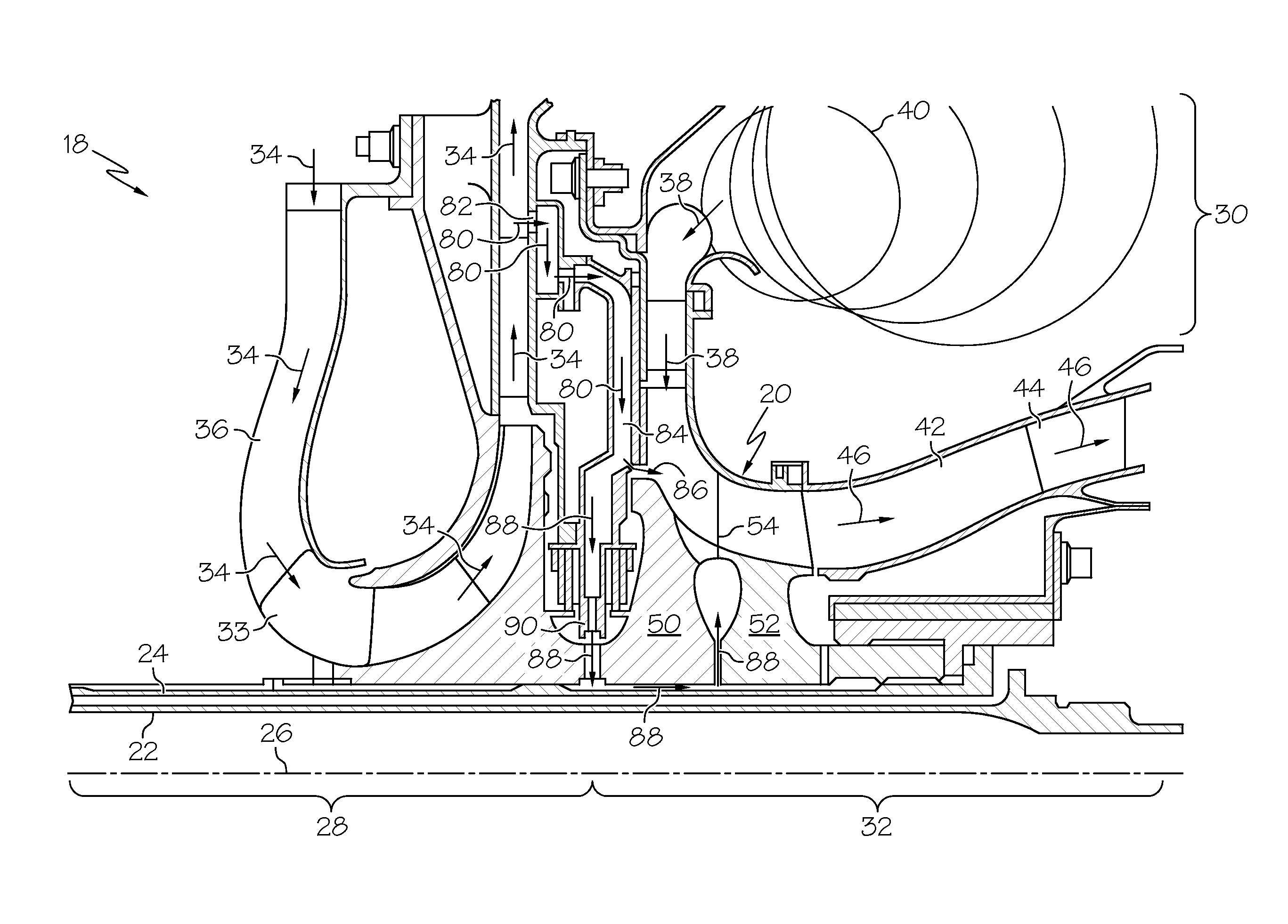
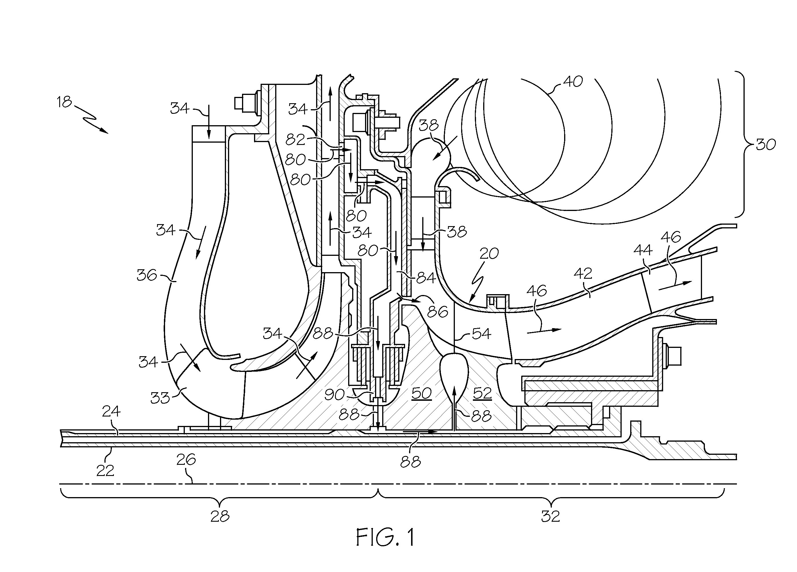
[0020]FIG. 1 is a simplified cross-sectional view of a portion of a gas turbine engine (GTE) 18 including an internally-cooled, axially-split radial turbine 20, as illustrated in accordance with an exemplary embodiment of the present invention. The term “axially-split radial turbine,” as appearing herein, is utilized in a broad sense to denote a radial turbine that includes or that is fabricated from at least two axially-mating or axially-abutting structures or sections. As illustrated in FIG. 1 and described herein, GTE 18 is offered by way of example only to provide a convenient and non-limiting context in which an exemplary embodiment of radial turbine 20 can be readily understood. It wil...


PUM

PropertyMeasurementUnit
thicknessaaaaaaaaaa
thicknessaaaaaaaaaa
temperatureaaaaaaaaaa

Abstract

Embodiments of an axially-split radial turbine, as are embodiments of a method for manufacturing an axially-split radial turbine. In one embodiment, the method includes the steps of joining a forward bladed ring to a forward disk to produce a forward turbine rotor, fabricating an aft turbine rotor, and disposing the forward turbine rotor and the aft turbine rotor in an axially-abutting, rotationally-fixed relationship to produce the axially-split radial turbine.

Description

TECHNICAL FIELD[0001]The present invention relates generally to gas turbine engines and, more particularly, to axially-split radial turbines for usage within gas turbine engines, as well as to methods for fabricating axially-split radial turbines.BACKGROUND[0002]Gas turbine engines (“GTE”) have been engineered extensively to improve efficiency, thrust-to-weight ratios, and other measures of engine performance. One of the most direct manners by which engine performance can be improved is through increases in core rotational speeds and turbine inlet temperatures generated during engine operation. However, as turbine inlet temperatures and rotational speeds increase, so too do the thermal and mechanical demands placed on the GTE components. The most demanding performance requirements are typically placed on the high pressure turbine rotor or rotors, which are positioned immediately downstream of the GTE combustion section and which rotate at the greatest speed during engine operation. ...

Claims


Application Information

Patent Timeline
Patent Type & Authority Applications(United States)
IPC IPC(8): F01D5/02B23P15/04F01D5/14
CPCF01D5/04F01D5/066F01D5/088F01D5/18F05D2230/60Y10T29/49323Y10T29/49321Y10T29/49341Y02T50/60B23P15/006F01D5/045F01D5/046F01D5/048F01D5/187F01D5/30F01D5/147F01D5/28
Inventor MITTENDORF, DONJAN, DAVID K.SMOKE, JASONMINER, AMANDINE
Owner HONEYWELL INT INC
Why Eureka
Try Eureka