Radial turbine rotor blade

A moving blade and radial flow technology, which is applied to the supporting components of the blades, non-variable engines, engine components, etc., can solve the problems of reducing impact loss efficiency, etc., and achieve the effect of reducing impact loss and improving turbine efficiency

Active Publication Date: 2015-08-19
MITSUBISHI HEAVY IND LTD
View PDF5 Cites 10 Cited by
  • Summary
  • Abstract
  • Description
  • Claims
  • Application Information

AI Technical Summary

Problems solved by technology

Therefore, leakage flow from the pressure surface side 31 to the negative pressure surface side 29 will occur, excessive peeling will occur on the negative pressure surface side 29, impact loss will occur, and the efficiency will be reduced.

Method used


Image

  • Radial turbine rotor blade
  • Radial turbine rotor blade
  • Radial turbine rotor blade

Examples


no. 1 approach

[0072] refer to figure 1 , the first embodiment of the present invention will be described.

[0073] First, refer to Figure 10A , Figure 10B The variable capacity exhaust turbocharger 3 using the radial turbine 1 will be described. As shown in the figure, a spiral scroll 7 is formed in the turbine housing 5, and a gas outlet passage 9 is formed on the inner peripheral side. In addition, a compressor housing and a turbine housing with a compressor not shown are formed. 5 and the bearing shell 11.

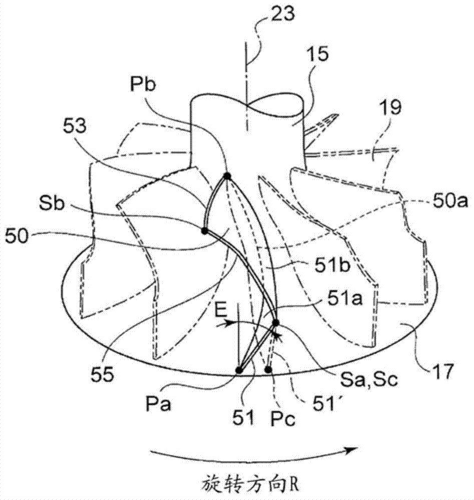
[0074] The turbine rotor 13 is composed of a hub 17 fixed to an end portion of a rotor shaft 15 and a plurality of rotor blades 50 fixed at equal intervals in the circumferential direction on the outer periphery of the hub 17 . Furthermore, a compressor (not shown) is connected to the rotor shaft 15 on the opposite side to the turbine rotor 13 .

[0075] Furthermore, a compressor (not shown) is connected to the opposite side of the rotor shaft 15 . A bearing 21 that supports ...

no. 2 approach

[0091] refer to figure 2 , 3 , and the second embodiment will be described.

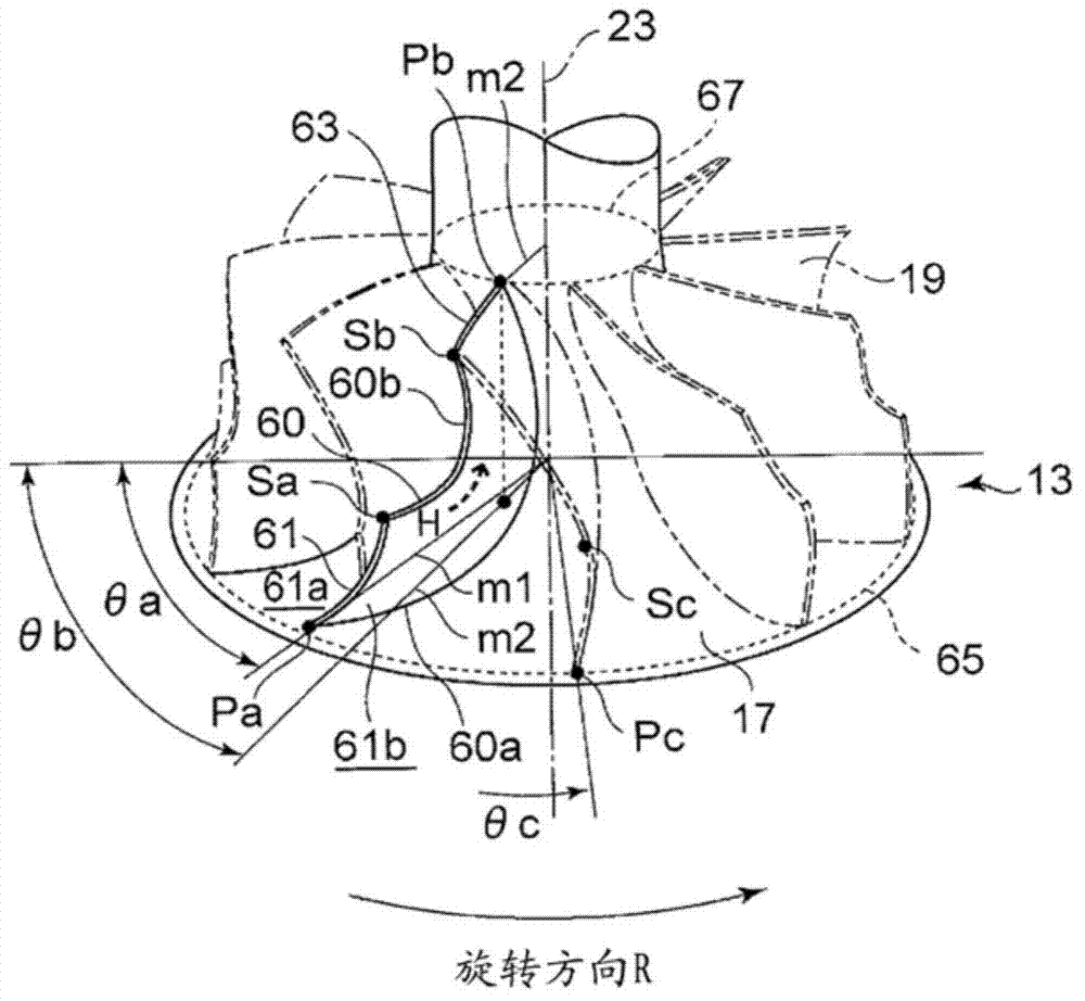
[0092] The first embodiment is characterized in that the shape of the leading edge 51 is formed by the inclination of the straight line connecting the leading edge shroud position Sc and the leading edge hub position Pa. In contrast, the second embodiment is characterized in that The positional relationship between the leading edge 61 side and the trailing edge 63 side on the hub joint line 60 a indicating the connection position of the rotor blade 60 to the upper surface of the hub 17 is also specified.

[0093] like figure 2 As shown, the line segment m1 connecting the leading edge hub position Pa on the leading edge hub circle 65 and the rotation centerline 23 of the moving blade 60 is more than the line segment m1 connecting the trailing edge hub position Pb on the trailing edge hub circle 67 and the The line segment m2 connecting the rotation centerlines 23 is located on the front side of t...

no. 3 approach

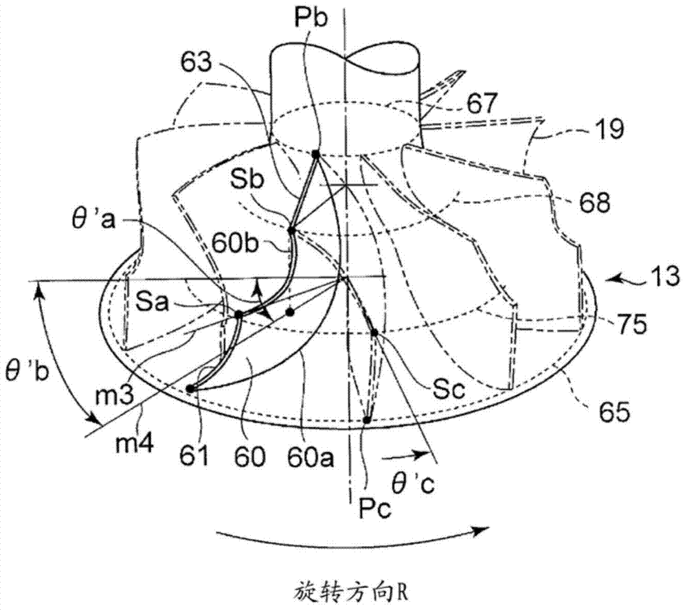
[0105] A third embodiment will be described with reference to FIG. 4 .

[0106] The third embodiment is characterized in that the shape of the front edges 51 , 61 of the rotor blade 50 of the first embodiment or the rotor blade 60 of the second embodiment is formed into a substantially linear shape.

[0107] As shown in FIG. 4 , a line segment connecting the leading edge shroud positions Sa, Sc and the leading edge hub position Pa is formed in a substantially linear shape.

[0108] As described above, by forming the rotor blades 50 and 60 in a linear shape, the load in the blade height direction becomes uniform, and the generation of unnecessary secondary flows can be suppressed.


PUM


Abstract

[Problem] To provide a radial turbine rotor blade whereby, even if a variable nozzle mechanism in a variable-geometry turbocharger is closed down, resulting in a flow field with a low turbine velocity ratio (U/C0), inflowing-gas impact losses at the leading edge of the rotor blade are reduced, improving turbine efficiency. [Solution] This radial turbine rotor blade is characterized in that: with respect to the direction of rotation (R) of the rotor blade (50), the hub-side corner (Pa) of the leading edge (51) of the rotor blade (50) is behind the shroud-side corner (Sc) of said leading edge (51); and in a radial view of the rotor blade (50), a line that connects the aforementioned shroud-side corner (Sc) to the hub-side corner (Pa) forms a 30-70° angle with a line that extends in the direction of the axis of rotation from the shroud-side corner (Sc) of the leading edge (51) to the surface of the hub (17).

Description

technical field [0001] The invention relates to a radial flow turbine moving blade, which is used for exhaust turbochargers of internal combustion engines, small gas turbines, expansion turbines, etc. After radial flow flows into the turbine rotor blades and acts on the rotor blades, the turbine rotor is driven to rotate by letting it flow out in the axial direction. Background technique [0002] With respect to the exhaust gas turbocharger for automobiles, due to the strengthening of the exhaust restriction, the improvement of the low-speed response of the engine is emphasized, and a high responsiveness of the turbocharger is desired. [0003] When the engine accelerates, the exhaust pressure first increases to supply energy to the turbine, and then the number of revolutions of the turbine increases. Therefore, the pressure ratio between the inlet and outlet of the turbine moving blades increases, so that the turbine operating speed ratio (U / C0) is greatly reduced compared...

Claims


Application Information

Patent Timeline
Patent Type & Authority Applications(China)
IPC IPC(8): F02B39/00F01D5/04F02B37/24
CPCF01D5/14F02B37/24F01D5/141F01D5/04F01D1/22F02C6/12F01D25/24F05D2220/30F05D2240/301
Inventor 横山隆雄东条正希永江聪美
Owner MITSUBISHI HEAVY IND LTD
Why Eureka
Try Eureka