High-efficiency gas and liquid mixer for gas and liquid two-phase flow experiment

A gas-liquid two-phase flow, gas-liquid mixer technology, applied in the direction of fluid mixer, mixer, mixing method, etc., can solve the flow state disorder of the produced gas-liquid mixture, increase the contact area of ​​gas and liquid, and flow loss. Large and other problems, to achieve the effect of uniform stress distribution, reduction of impact loss, and reduction of resistance loss

Active Publication Date: 2016-12-14
JIANGSU UNIV ZHENJIANG RES INST OF FLUID ENG EQUIP TECH
View PDF8 Cites 4 Cited by
  • Summary
  • Abstract
  • Description
  • Claims
  • Application Information

AI Technical Summary

Problems solved by technology

[0003] Aiming at the problems of large flow loss and turbulent flow state of the produced gas-liquid mixture in the current gas-water mixing device, the present invention adds three-layer composite hollow structure gas transmission partitions I to IV in the gas transmission pipeline, and the gas transmission partitions The front and rear parts of plates Ⅰ~Ⅳ are respectively equipped with angle of attack and shrinking nozzles. The angle of attack is beneficial to reduce the resistance loss of flow, and the nozzle can effectively increase the contact area of ​​gas and liquid; The outlets of plates Ⅰ~Ⅳ can achieve the same flow state, and the inlet cross-sectional area of ​​the nozzle is designed; in order to reduce the impact loss in the flow, the guide vanes are arranged symmetrically in the sleeve to guide the flow; the design is fully considered as The impact loss when the gas enters the gas transmission partitions Ⅰ~Ⅳ, based on this, the inlet and guide vane length of the gas transmission partitions Ⅰ~Ⅳ are calculated, so that the gas can enter the gas transmission partition smoothly and quickly

Method used


Image

  • High-efficiency gas and liquid mixer for gas and liquid two-phase flow experiment
  • High-efficiency gas and liquid mixer for gas and liquid two-phase flow experiment
  • High-efficiency gas and liquid mixer for gas and liquid two-phase flow experiment

Examples


Embodiment Construction

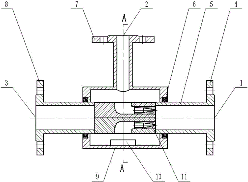
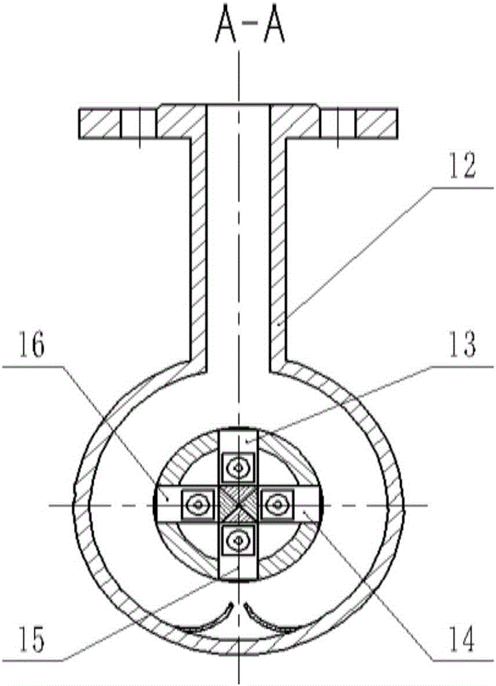
[0036] The specific implementation method of the present invention is now described in conjunction with the accompanying drawings: In order to meet the observation requirements of the test bench, an embodiment of the present invention is processed by using organic glass with good transparency and stable chemical properties. In order to realize the gas-liquid mixing function, the gas-water mixer adopts a horizontal three-way structure, and the three inlet and outlet ports are all equipped with flanges. The inlet flange 2 is connected to the sleeve 9 through the inlet pipe 12, the inlet flange 4 is connected to the outlet flange 8 through the main flow pipe 5, the sleeve 9 is coaxially sleeved outside the main flow pipe 5, and the inside of the sleeve 9 is far away from the inlet port. There are two guide vanes 10 arranged symmetrically, sealing grooves are opened at the left and right ends of the sleeve 9, and a skeleton oil seal 7 is used to seal the contact surface between the...


PUM


Abstract

The invention relates to a gas and liquid mixer, in particular to a high-efficiency gas and liquid mixer for a gas and liquid two-phase flow experiment table. The high-efficiency gas and liquid mixer is characterized in that gas conveying separating plates are arranged in a main flow pipe, and are used for conveying gas phase, and an angle of attack at the front part of each gas conveying separating plate is favorable for the flowing of fluid, so as to reduce the resistance loss; a shrinkage type spray pipe is arranged at the tail part of each gas conveying separating plate, and the inlet cross section is designed, so that the air flow which flows out of each spray nozzle has the same outlet state; under the spraying action of spray pipes, the contact area of gas and liquid is increased, the mixing is uniform, and the stress produced by mixing is uniformly distributed when each gas conveying separating plate is arranged in an axis symmetric way; guide vanes which are symmetrically arranged in a sleeve cylinder are used for guiding flow, so that the impact loss of flowing is reduced; after calculating, the inlet length of each gas conveying separating plate, and the value range of the length of each guide vane are obtained, so that the impact loss of flowing is reduced, and the stable flowing state is furthest maintained.

Description

technical field [0001] The invention relates to a gas-liquid mixer, in particular to a high-efficiency gas-liquid mixer used in a gas-liquid two-phase flow test bench. Background technique [0002] Gas-liquid two-phase fluid mechanics is a new branch of fluid mechanics, which studies the flow law of gas and liquid two-phase media under the condition of common flow. The study of gas-liquid two-phase flow is closely related to the progress of engineering technology. At the end of the nineteenth century, the research on boiler and water circulation problems has already involved the flow of gas-liquid two-phase flow. In the 1930s, according to the needs of production development, the research work on gas-liquid two-phase flow was carried out increasingly. After 1950, with the introduction of medium, high temperature and high pressure parameters in the power industry, and the development of aerospace and nuclear power industries, more in-depth research was carried out on the flo...

Claims


Application Information

Patent Timeline
Patent Type & Authority Applications(China)
IPC IPC(8): B01F5/04B01F3/04
CPCB01F23/2319B01F25/31322B01F25/3133
Inventor 朱荣生王海彬王秀礼付强王学吉张本营
Owner JIANGSU UNIV ZHENJIANG RES INST OF FLUID ENG EQUIP TECH
Why Eureka
Try Eureka