Two-channel variable-section volute device with flow-guiding blades

A guide vane, dual-channel technology, used in engine components, machines/engines, internal combustion piston engines, etc., can solve problems such as wall friction loss, lack of improvement in airflow characteristics, and achieve good inheritance, easy control, and improved performance. The effect of efficiency

Active Publication Date: 2012-07-11
康跃科技(山东)有限公司
View PDF9 Cites 5 Cited by
  • Summary
  • Abstract
  • Description
  • Claims
  • Application Information

AI Technical Summary

Problems solved by technology

However, the designed structure: the runner ribs only play the role of fixed support connection, in addition, there will be a certain wall friction loss on the wall of the runner ribs, and it does not have the characteristics of improving the airflow characteristics

Method used


Image

  • Two-channel variable-section volute device with flow-guiding blades
  • Two-channel variable-section volute device with flow-guiding blades
  • Two-channel variable-section volute device with flow-guiding blades

Examples


Embodiment 1

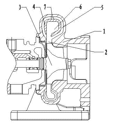
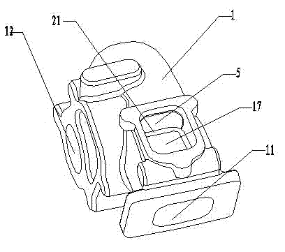
[0041] Example 1, such as image 3 , Figure 4 As shown, a double-channel variable-section volute device with guide vanes includes a volute 1, and the volute 1 is provided with a volute air inlet 11, a volute air outlet 12, and a volute air intake channel and Volute diffuser channel 2;

[0042] The volute air intake channel is provided with a pneumatic partition 13, and the aerodynamic partition 13 divides the volute air intake channel into the volute air intake inner channel 6 and the volute air intake outer channel 5;

[0043] The volute air intake outer flow channel 5 is located on the circumferential outer side of the volute air intake inner flow channel 6;

[0044] Vaneless nozzles 15 are respectively provided at the positions of the volute air intake outer flow channel 5 and the volute air intake inner flow channel 6 close to the volute diffuser passage 2;

[0045] A plurality of airfoil-shaped aerodynamic guide vanes 14 are evenly arranged in a circular shape near th...

Embodiment 2

[0059] Example 2, such as Figure 6 As shown, in order to be applicable to a pulse supercharging system, such as a six-cylinder engine, in the above-mentioned embodiment 1, the volute air inlet 11 can also be designed as a double air inlet: comprising the air inlet 24 on the left side of the volute and the volute Right air intake 25.

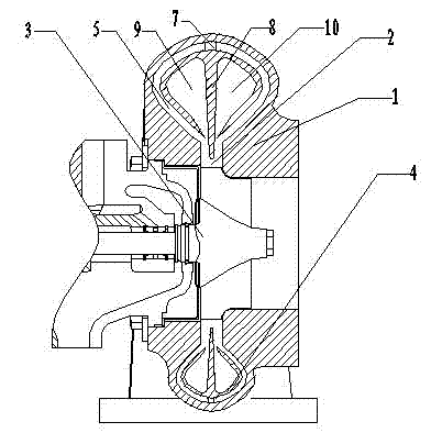
[0060] Such as Figure 7 As shown, the volute intake inner flow channel 6 is provided with a pulse inner flow channel rib 8, and the pulse inner flow channel rib 8 divides the volute intake inner flow channel 6 into the left pulse inner flow channel 9 And the inner runner 10 of the pulse on the right side.

[0061] The left pulse inner flow channel 9 and the right pulse inner flow channel 10 are respectively connected with the left air inlet 24 of the volute and the right air inlet 25 of the volute.

[0062] The cross-section of the pulse internal flow channel rib 8 is tapered, and the pulse internal flow channel rib 8 is connected with the p...


PUM


Abstract

The invention discloses a two-channel variable-section volute device with flow-guiding blades, which comprises a volute. A volute air inlet, a volute air outlet, a volute air inlet flow channel and a volute diffusing channel are arranged in the volute, a pneumatic partition plate is arranged in the volute air inlet flow channel and divides the volute air inlet flow channel into a volute air inlet inner flow channel and a volute air inlet outer flow channel, the volute air inlet outer flow channel is located on the outer side of the circumference of the volute air inlet inner flow channel, and the position of the volute air inlet outer flow channel and the position of the volute air inlet inner flow channel which are close to the volute diffusing channel are respectively provided with a no-blade nozzle. A plurality of wing-shaped pneumatic flow-guiding blades are annularly evenly arranged at the position inside the volute air inlet outer flow channel close to the no-blade nozzle. For a pulse pressurizing system, the inner flow channel works at an engine low-speed area, and the pulse energy can be utilized better. When at a high speed, the outer flow channel does not need to be divided into two flow channels, enough energy can be obtained through one flow channel, a product structure is further simplified, and the product weight is reduced.

Description

technical field [0001] The invention relates to a double-channel variable-section volute device, in particular to a double-channel variable-section volute device with guide blades for improving supercharger efficiency, and belongs to the field of internal combustion engine supercharging. Background technique [0002] In recent years, with the increasingly stringent requirements of emission regulations, people's demand for turbochargers that take into account both high and low speed performance of the engine has become more and more intense. The dual-channel variable cross-section turbocharger that meets the performance requirements of the engine in the full range of operating conditions has become The focus of research on the internal combustion engine industry. [0003] Such as figure 1 As shown, patent CN200910016706.6 discloses a structure of embodiment 1 of a turbocharger double-layer channel variable-section turbine, including a volute 1, a volute diffuser channel 2, a...

Claims


Application Information

Patent Timeline
Patent Type & Authority Applications(China)
IPC IPC(8): F01D25/24F01D17/16F02B37/24
CPCY02T10/144Y02T10/12
Inventor 王航李永泰王艳霞袁道军李伟高小青
Owner 康跃科技(山东)有限公司
Why Eureka
Try Eureka