Centrifugal turbomachinery

a centrifugal turbomachinery and centrifugal technology, applied in the direction of machines/engines, stators, liquid fuel engines, etc., can solve the problems of difficult to freely select both elements, unstable phenomenon, and difficult to optionally select the blade number of the diffuser, so as to reduce the impact loss, reduce the fluid loss, and reduce the fluid performance

Active Publication Date: 2007-09-20
HITACHI IND PROD LTD
View PDF3 Cites 6 Cited by
  • Summary
  • Abstract
  • Description
  • Claims
  • Application Information

AI Technical Summary

Benefits of technology

[0009] In accordance with the present invention, since the outer diameter position of the return flow path is changed in the peripheral direction in the centrifugal turbomachinery, it is possible to lower an impact loss and the like in the blade of the return flow path, and it is possible to lower a fluid loss. Further, since it is possible to shift the return flow path to the inner diameter side without lowering the fluid performance, it is possible to achieve a compact structure.

Problems solved by technology

In the fluid machinery described in the publication mentioned above, it is possible to optionally select the blade number of the water return blade, however, it is hard to necessarily optionally select the blade number of the diffuser due to the following reasons.
If the stall of the flow is generated in the diffuser, an unstable phenomenon is generated in a head curve.
As a result, the blade numbers of the diffuser and the return blade are closely related with each other, and it is impossible to freely select both the elements.

Method used


Image

  • Centrifugal turbomachinery
  • Centrifugal turbomachinery
  • Centrifugal turbomachinery

Examples


Embodiment Construction

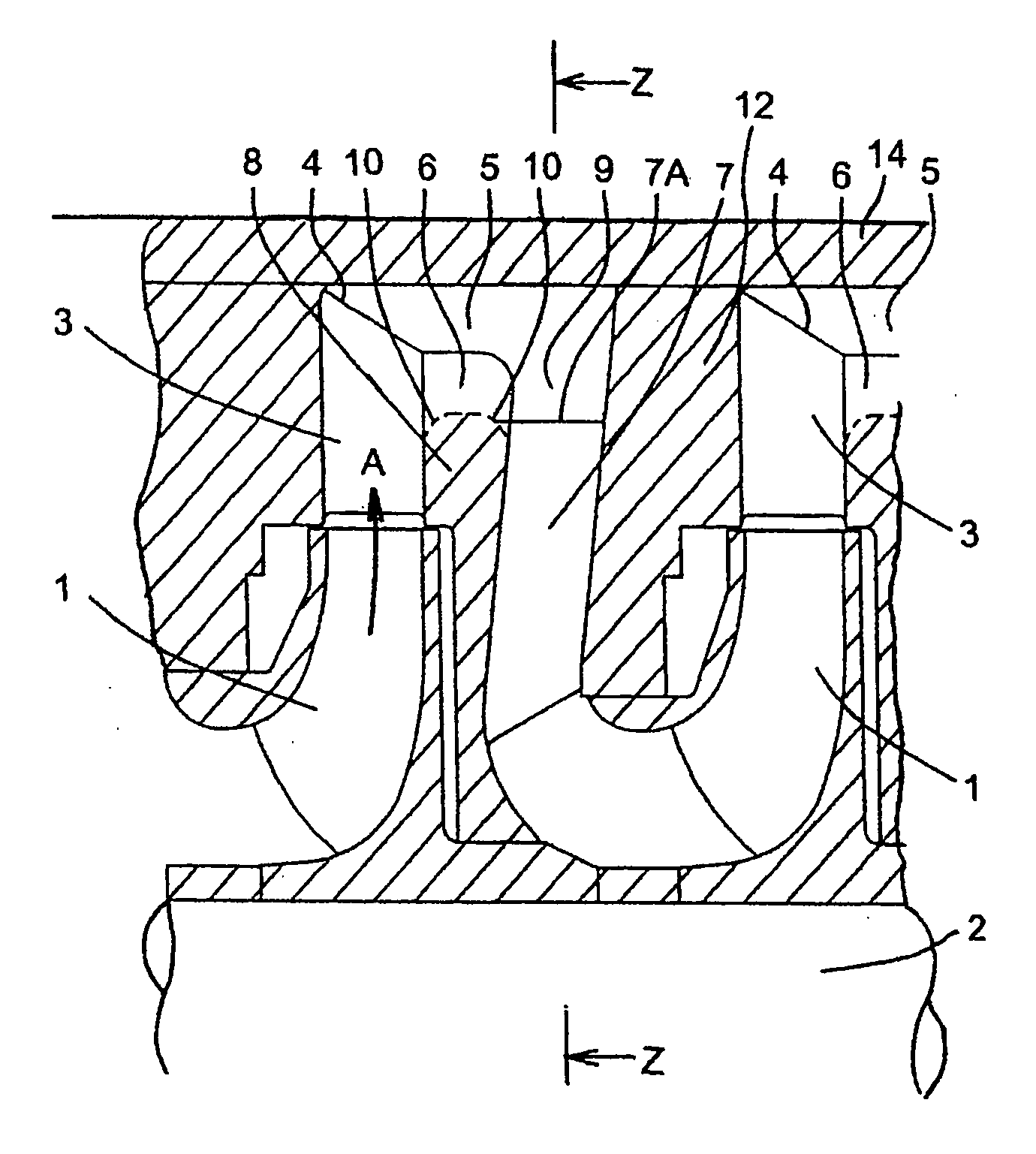
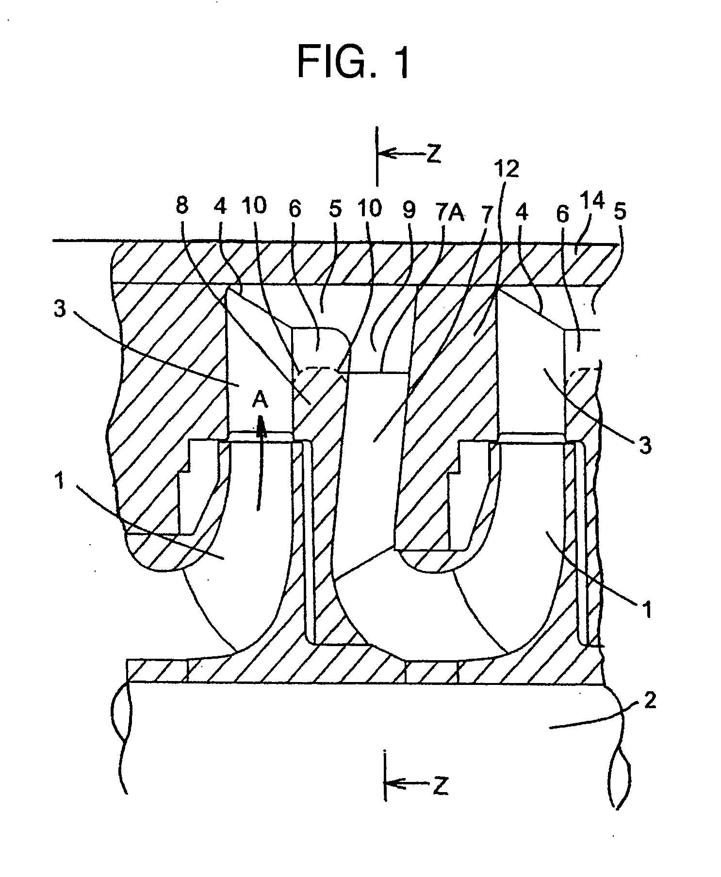
[0014] A description will be given below of several embodiments of a centrifugal turbomachinery in accordance with the present invention with reference to the accompanying drawings. In the following description, a centrifugal pump is exemplified, however, the present invention can be applied in the same manner to every centrifugal turbomachinery. An example of a centrifugal pump 100 is shown in FIGS. 1 and 2. FIG. 1 is a vertical cross sectional view of a main portion of a one-axis multi-stage centrifugal pump, and shows adjacent two stage portions in a middle position.

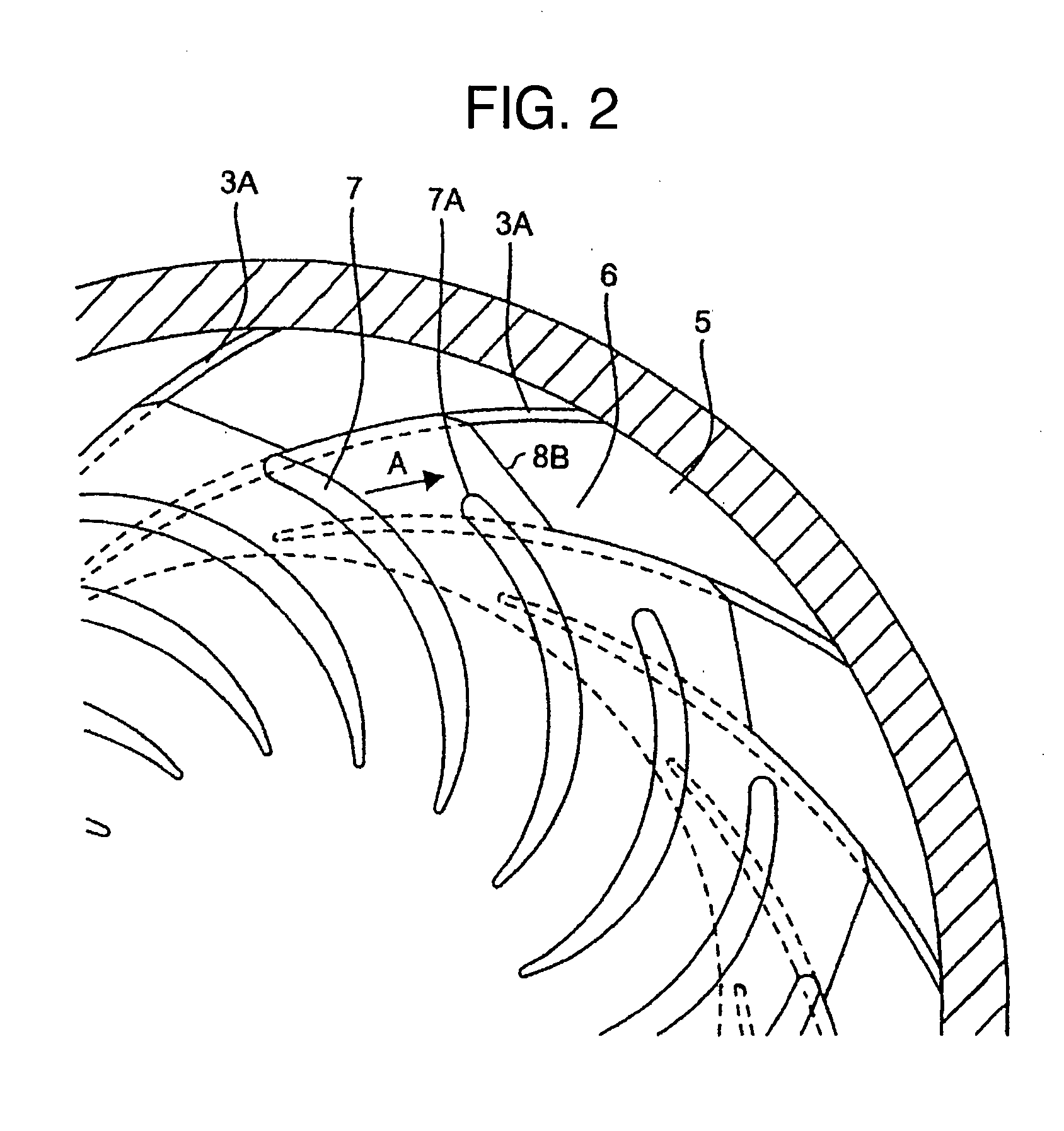
[0015]FIG. 2 is a horizontal cross section of a water return portion of the centrifugal pump 100 shown in FIG. 1, and corresponds to a view as seen from an arrow Z-Z in FIG. 1.

[0016] A plurality of impellers 1 are attached to a main shaft 2 coupled to a driving machine (not shown). A diffuser 3 formed by a pair of parallel wall surfaces is formed in a downstream side corresponding to an outer side in a radial direct...


PUM


Abstract

A centrifugal turbomachinery in accordance with the present invention can lower a fluid loss in a return flow path. In the centrifugal turbomachinery, a plurality of centrifugal impellers is attached to a rotating shaft, and the centrifugal turbomachinery is provided with a diffuser having a plurality of blades introducing a fluid boosted by a front stage impeller to a rear stage impeller, and a return flow path means. The return flow path means has a side plate arranged in a back surface side of the front stage impeller, a plate opposing the side plate and arranged in a front surface side of the rear stage impeller, and a plurality of blades arranged between the side plate and the plate so as to be spaced in a peripheral direction. A maximum diameter portion of the side plate is changed in the peripheral direction.

Description

BACKGROUND OF THE INVENTION [0001] The present invention relates to a turbomachinery such as a pump and a compressor, and more particularly to a centrifugal turbomachinery flowing out a fluid in a centrifugal direction from an impeller. [0002] An example of a conventional centrifugal turbomachinery is disclosed in JP-A-11-324987. In the centrifugal turbomachinery disclosed in this publication, in order to downsize without lowering a fluid performance, on inlet end portion of return blades is located in an inner side in a radial direction than a position in a radial direction of a semi-open portion passage. Further, a circular pipe shaped space continuously provided with the semi-open portion passage is formed in an outer side in the radial direction than the return blade inlet side end portion. Accordingly, a stream flowing out from the semi-open portion passage can flow in without being regulated by a plurality of return blades arranged in a peripheral direction so as to form a cir...

Claims


Application Information

Patent Timeline
Patent Type & Authority Applications(United States)
IPC IPC(8): F04D29/44
CPCF04D29/445F04D1/063F04D29/448F04D29/441F04D17/125F04D29/24F04D29/30F04D29/669F04D29/667F05D2210/11F05D2210/12
Inventor AKI, TAKASHIMANABE, AKIRATANAKA, SADASHIFUKUCHI, TAKAKI
Owner HITACHI IND PROD LTD
Why Eureka
Try Eureka